Sand Casting
In sand casting, reusable, permanent patterns are used to make the sand moulds. The preparation and the bonding of this sand mould are the critical steps and very often are the rate-controlling step of this process. Two main routes are used for bonding the sand moulds:
• The "green sand" consists of mixtures of sand, clay and moisture.
• The "dry sand" consists of sand and synthetic binders cured thermally or chemically.
The sand cores used for forming the inside shape of hollow parts of the casting are made using dry sand components.
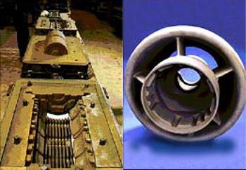
This versatile technique is generally used for high-volume production. An example of half sand mould is given in Figure 1.
|

|
|
Figure 1. Half mould with cores and an example of a cast air intake for a turbocharger.
|
Normally, such moulds are filled by pouring the melted metal in the filling system. Mould designing is a particularly complex art and is based on the same principle as gravity die casting, illustrated in Figure 4.
In the "low pressure" sand casting technique, the melted metal is forced to enter the mould by low-pressure difference. This more complicated process allows the production of cast products with thinner wall thickness.
Die Casting Aluminium
In this technique, the mould is generally not destroyed at each cast but is permanent, being made of a metal such as cast iron or steel. There are a number of die-casting processes, as summarised in Figure 2. High-pressure die casting is the most widely used, representing about 50% of all light alloy casting production.
Low-pressure die casting currently accounts for about 20% of production, and its use is increasing. Gravity die casting accounts for the rest, with the exception of a small but growing contribution from the recently introduced vacuum die casting and squeeze casting process.
|

|
|
Figure 2. Classifications of die casting processes.
|
Gravity Casting
A schematic view in Figure 3 shows the main parts constituting a classical mould for gravity die casting. Cores (inner parts of the mould) are generally made of bonded sand.
|

|
|
Figure 3. Schematic view of the components of a casting mould (gravity die casting).
|
Gravity die casting is suitable for mass production and fully mechanised casting.
High-Pressure Die Casting
In this process, the liquid metal is injected at high speed and high pressure into a metal mould. A schematic view of high pressure die casting is given in Figure 4.
|

|
|
Figure 4. Schematic view of a high pressure die casting machine.
|
This equipment consists of two vertical platens on which bolsters are located, which hold the die halves. One plate is fixed, and the other can move so that the die can be opened and closed. A measured amount of metal is poured into the shot sleeve and then introduced into the mould cavity using a hydraulically-driven piston. Once the metal has solidified, the die is opened and the casting is removed.
In this process, special precautions must be taken to avoid too many gas inclusions, which cause blistering during subsequent heat treatment or welding of the casting product.
Both the machine and its dies are very expensive, and for this reason, pressure die casting is economical only for high-volume production.
Low-Pressure Die Casting
As schematised in Figure 5, the die is filled from a pressurised crucible below, and pressures of up to 0.7 bar are usual. Low-pressure die casting is especially suited to the production of components that are symmetric about an axis of rotation. Light automotive wheels are normally manufactured by this technique.
|

|
|
Figure 5. Schematic view of a low pressure die casting machine.
|
Vacuum Die Casting
The principle is the same as low-pressure die casting. The pressure inside the die is decreased by a vacuum pump and the difference of pressure forces the liquid metal to enter the die. This transfer is less turbulent than by other casting techniques so that gas inclusions can be very limited. As a consequence, this new technique is specially aimed to components which can subsequently be heat-treated.
Squeeze Casting or Squeeze Forming
As shown in Figure 6, liquid metal is introduced into an open die, just as in a closed-die forging process. The dies are then closed. During the final stages of closure, the liquid is displaced into the further parts of the die. No great fluidity requirements are demanded of the liquid since the displacements are small. Thus forging alloys, which generally have poor fluidities which normally preclude the casting route, can be cast by this process.
|

|
|
Figure 6. The squeeze casting principle.
|
This technique is especially suited for making fibre-reinforced castings from fibre cake preform. Squeeze casting forces liquid aluminium to infiltrate the preform. In comparison with non-reinforced aluminium alloy, aluminium alloy matrix composites manufactured by this technique can double the fatigue strength at 300°C. Hence, such reinforcements are commonly used at the edges of the piston head of a diesel engine where solicitations are particularly high.
Conclusions
Aluminium castings are very powerful and versatile techniques for manufacturing semi- or finished products with intricate shapes. Those techniques are continuously improved and developed to satisfy the user needs and to penetrate new markets.
Innovations are mainly oriented to the automobile sector which is the most important market for castings. This continual improvement and development will ensure that aluminium castings continue to play a vital role in this field.
|