| Amorphous (a-C) and hydrogenated amorphous carbon (a-C:H) films have high hardness, low friction, electrical insulation, chemical inertness, optical transparency, biological compatibility, ability to absorb photons selectively, smoothness, and resistance to wear. For a number of years, these economically and technologically attractive properties have drawn almost unparalleled interest towards these coatings. Carbon films with very high hardness, high resistivity, and dielectric optical properties, are now described as diamond-like carbon or DLC, table 1. Table 1. Properties of diamond and DLC materials. | | | Crystal Structure | Cubic
ao=3.561Å | Amorphous
Mixed sp2 and sp3 bonds | Amorphous
sp3/sp2 | Cubic
ao=3.567Å | Hexagonal
a=2.47 | | Form | Faceted crystals | Smooth or rough | Smooth | Faceted crystals | | | Hardness (Hv) | 3000-12000 | 1200-3000 | 900-3000 | 7000-10000 | | | Density (g/cm3) | 2.8-3.5 | 1.6-2.2 | 1.2-2.6 | 3.51 | 2.26 | | Refractive Index | - | 1.5-3.1 | 1.6-3.1 | 2.42 | 2.15 | | Electrical Resistivity (Ω/cm) | >1013 | >1010 | 106-1014 | >1016 | 0.4 | | Thermal Conductivity (W/m.K) | 1100 | - | - | 2000 | 3500 | | Chemical Stability | Inert | Inert | Inert | Inert | Inert | | Hydrogen Content (H/C) | - | - | 0.25-1 | - | - | | Growth Rate (µm/hr) | ~1 | 2 | 5 | 1000 (synthetic) | - | Methods for Producing DLC Films Several methods have been developed for producing diamond-like carbon films: • primary ion beam deposition of carbon ions (IBD) • sputter deposition of carbon with or without bombardment by an intense flux of ions (physical vapour deposition or PVD) • deposition from an RF plasma, sustained in hydrocarbon gases, onto substrates negatively biased (plasma assisted chemical vapour deposition or PACVD). Until recently, the work on DLC worldwide has not yielded the expected benefits in the field of wear resistance and general mechanical performance. Most of the success has been in applications for magnetic storage media and optical coatings. The reasons for this are: • only thin coatings (< 1µm) have been used • the 2D aspect of most of the deposition routes • the difficulty in gaining good adhesion to metallic substrates. Plasma Assisted CVD Plasma assisted CVD techniques employing RF and DC glow discharges in hydrocarbon gas mixtures produce smooth amorphous carbon and hydrocarbon films, which have mixed sp2 and sp3 bonds. These exhibit hardness values of 900-3000Hv. The CVD processes will generally require deposition temperatures of at least 600°C to give the required combination of properties, however, low temperature deposition is possible. The CVD technique gives good deposition rates and very uniform coatings, and is suited to very large-scale production. Ion Beam Deposition Another technique for DLC deposition is based on ion beam deposition. This has the advantage of being able to deposit high quality coatings at very low temperatures (near room temperature). The disadvantages are that the deposition rate is very low (1µm/hr maximum) and that even substrates of simple geometry need complex manipulation to ensure uniform deposition. The Closed Field Unbalanced Magnetron Sputter Ion Plating Process A technique has now been developed that can readily apply a-C:H films (>4µm) to substrates of any shape. The process is based on closed field unbalanced magnetron sputter ion plating (CFUBMS), figure 1, combined with plasma assisted chemical vapour deposition. The commercial importance of such a development is already being seen and the potential range of applications and possibilities are enormous. The technique is highly innovative and it provides the flexibility required to ensure excellent adhesion to any substrate, and the coating of any component shape or material, in a high productivity industrial process. | 
| | Figure 1. Schematic of a four magnetron closed field unbalanced magnetron sputtering system (DG Teer, UK Patent 2258343A) | The new technique combines the benefits of both plasma CVD and ion beam deposition. The deposition is carried out at 200°C in a closed field unbalanced magnetron sputter ion plating system (Teer Coatings UDP 400 or 800 series). The system was originally designed for reactive deposition of metal nitrides, carbides and oxides. The inherent versatility of the process has enabled the deposition of DLC in the system by combining two established techniques, PVD and CVD. Low pressure RF plasma CVD is adopted for high rate deposition (>5µm/hr), in combination with simultaneous ion assistance and physical vapour deposition from unbalanced magnetron sputtering sources, to give very high quality films. As with beam techniques, the low pressure of the process means that deposition is to some extent line-of-sight, which means that substrate manipulation is necessary to ensure uniform deposition. However, because the substrates are surrounded by four long magnetrons (>1m in length if necessary) the coating flux impinges on the substrates from all directions and, usually, only simple single axis rotation during deposition is necessary. Deposition of Stress-Free Films One of the main problems with DLC deposition at low temperature, is the creation of very high internal stress levels in the films. This, combined with the ensuing lattice mismatch when DLC is applied to a wide range of substrates, commonly leads to poor adhesion. In high mechanical stress applications, the adhesion of the films is of paramount importance. This problem has now been overcome by ensuring that there are no stress concentrations near the coating/substrate interface. The magnetron sources are used to reactively deposit a series of multilayer compounds prior to deposition of the DLC. The layers have graded interfaces. This ensures that there are no abrupt changes in composition, and that the stress is introduced into the film gradually. The optimum multilayer structure series is: titanium, titanium nitride, titanium carbonitride, titanium carbide, and then the DLC. It has also been subsequently found that the mechanical properties of the hard carbon films can be improved by incorporating a small percentage of metal dopant (usually ~5% titanium) in the final carbon structure. The resulting films have excellent friction and wear properties: • microhardness of up to 4000Hv • coefficient of friction during dry running in air against cemented WC always <0.15 • a wear rate 20% that of titanium nitride • exceedingly low counterface wear. Applications A wide variety of objects are now being coated, ranging from small items, to large dies and moulds. The rapidly expanding uses of the DLC films developed by the hybrid technique includes: • decorative/low friction coatings • coating of tools for the high speed machining of aluminium and copper alloys • ceramic washers in mixer taps • guides in textile processing machines • punches/dies • seals • cutting taps The coatings are shiny and black, and thus also offer high aesthetic appeal. Extrusion Dies The DLC based coatings are now highly successfully applied to a wide range of cold extrusion dies. In many cases it was necessary to pre-dip the mild steel billets in MOS2 before extrusion in an attempt to provide lubrication. In severe cases the dies needed repolishing after every billet because of pickup. The DLC coated dies now extrude 4000 billets (without pre-lubrication) and with no sign of wear. DLC coated punches can be seen in figure 2. | 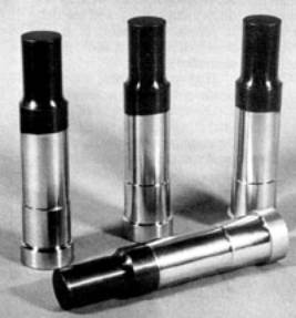
| | Figure2. Coated punches for high performance and extended lifetimes. | Engine Applications The coatings may well find their biggest application in enhancing properties of general wear parts. For example, it was hoped that the coating of cams and cam followers with DLC in Formula 1 motorbike engines would produce an increase in power of 0.5-1bhp. The resulting power increase was 8bhp, which in racing terms is enormous. Bone Saws The coating of medical saws for bone cutting showed that after using the saws for double the normal lifetime no wear was apparent. But more importantly because of the low frictional heating and quality of cut, the amount of bone necrosis (killing of the bone tissue) was reduced so effectively, that new bone tissue was able to ‘take’ to the cut area very easily. A new and very important field where the carbon films appear to perform very well, is the machining of stainless steel. Titanium nitride coated tools offer very little benefit in this area of machining. The use of carbon based coatings, such as TiCN, for machining ferrous based alloys, has always been unsuccessful owing to the reaction between the carbon in both coating and ferrous workpiece. The difficult job of machining stainless steel is therefore carried out with uncoated tools at low feeds and speeds. When the new carbon coatings (DLC with 5% titanium) were tested under similar conditions, there was on average a fourfold increase in drill life over the other coated and uncoated drills, figure 3. The coatings tested were not optimised in any way for the application, so tool lives up to the maximum 10 times and beyond are now possible. | 
| | Figure 3. Comparison of performance of uncoated, titanium nitride coated and DLC (~5% Ti) coated drills during stainless steel machining. Cutting speed 16m/min, feed rate 0-30mm/rev, blind holes 18mm depth, water-soluble coolant. | Summary As has been demonstrated, the application of a well adhered, very hard, low friction and wear DLC based coating to a wide variety of mechanical parts is bound to produce economic benefits. In many applications, the now relatively modest coating cost that can be obtained, should far outreach the dramatic improvement in performance and life. |