Measurement of the rate of fluid flow is an important step in the processing industry. Choosing a suitable flow measurement technology is quite a challenge. In scenarios where many flow measurement technologies are suitable for a single application considering the energy cost savings can help narrow down the choices.
The various ways in which energy costs can be assessed for flowmeter technologies are described in this article.
Flowmeter Technologies
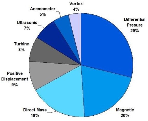
The different types of flowmeter technologies available and their level of usage in the processing industries are represented in the form of a flow chart (Figure 1).

Figure 1. Flowmeter technologies in the process industries.
Most of the technologies depicted in the figure: turbine, vortex, ultrasonic, electromagnetic and anemometers, actually determine the flow velocity of the fluid in the pipe. The volumetric flow rates can be determined as the product of the measured average flow velocity and the cross-sectional area of the pipe or meter. Restrictions in the flow of the fluid are introduced by flowmeters that operate based on differential pressure.
The different types of flowmeters are nozzles, wedges, pilot tubes, orifice plates and Venturi’s. The loss of pressure due to a restriction is unrecoverable and can be measured by the volumetric flow rate.
True volumetric flow can be measured using positive displacement flowmeters; they measure the actual fluid volume that passes via a meter body without taking the velocity into consideration. A specific volume of the fluid is captured by the flowmeter and passed into the outlet. The mechanism that empties the chamber and fills another is controlled by the fluid pressure.
Volumetric flow meters need to be given additional information like the fluid density, pressure, and/or temperature in order to measure the mass flow rate.
Additional sensors are provided in multivariable flowmeters and transmitters to obtain this information. The mass flow rate can be directly measured using Coriolis flowmeters and by thermal probes in the case of gas flows. The market share of these flowmeters is currently 18% and is poised to increase in future.
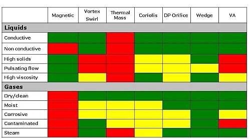
The suitability of specific flowmeter technologies for different liquid and gas conditions are depicted in Figure 2. It is evident that for a given set of fluid conditions, more than one technology is suitable. In these situations the selection can be narrowed down by considering the minimum energy costs.

Figure 2. Selection of flowmeter technologies depends on the application. Red = NO; Green = Yes and Yellow=maybe.
Need for Minimizing Energy
Pressure loss is induced in a system by most flowmeters, which translates to losses in energy and capital. Measurement devices like flowmeters, valves, pipe friction, expanders and reducers are contributing factors that increase the Permanent Pressure Loss (PPL) of the system. Upstream reducers and downstream expanders may be required for the hassle free operation of some flowmeters. PPL is a determining factor when designing systems for new processes.
Whilst designing a system for new processes engineers need to factor the PPL because the size of the pump (liquids), boiler (steam), or compressor (gas) is decided based on the PPL in order to meet the required process conditions and deliver the right pressure and/or flow.
The energy compensation in operating processes is also based on the PPL, and the energy compensation bears an influence on annual operating costs. The need for top-up pumping or compression can also impact on the environment can be controlled by minimizing these pressure losses. By replacing existing flowmeters with those with low pressure losses in an expensive steam boiler, its capacity can be improved.
Engineers can minimize the pumping or compression costs, increase the capacity and also minimize the footprint of the pump, compressor of boiler by choosing a flowmeter with low pressure losses.
The pressure loss in a flowmeter depends on the fluid density, the square of the fluid velocity (Vf)2 and the extent of obstruction to the fluid flow (Kmeter). The magnitude of the Kmeter for different flowmeters is ranked below, from the highest pressure loss to the lowest.
- Coriolis
- Orifice/Nozzle
- Turbine
- Vortex
- Venturi
- Averaging Pitot tube
- Electromagnetic/ Ultrasonic (negligible PPL)
Based on the above rankings, when an orifice plate is replaced by an averaging pitot tube, the PPL and hence, the energy requirement or pressure loss can be brought down by a factor of 20. Averaging pitot tubes not only offer minimal PPL, but are also inexpensive and easy to install.
Examples of Energy Usage
The energy use per unit time can be calculated based on the permanent pressure loss (PPL), the volumetric flow (Q) and the mechanical efficiency (ME) of the system in decimals. With the power expressed in watts, PPLs in inches of water, and the volumetric flow in terms of CFM the following equation gives the value of energy use:
Power = (0.118 PPL * Q) / ME
The product of the decimal efficiencies of the electric motor and the compressor or pump is equal to the mechanical efficiency of the system. The system efficiency of boilers can be calculated in a similar manner. A system efficiency of 0.70 for nitrogen and 0.90 for water are assumed for the analyses below. Systems that have low efficiencies need additional power for compensating pressure losses in the process.
By multiplying the energy by the local cost of electricity ($/kwh) and the number of operating hours in a year (8,760 total hours per year), the annual cost can be calculated.
In the examples below, the cost per kilowatthhour is assumed to be $0.10, which is approximately equal to the national average in the year 2010. The value of the electric rate varies from 6 cents to 25 cents per kwh, depending on the state and the nature of use – commercial, industrial or residential.
Nitrogen, water and steam are considered as representative gases and liquids across many types of materials used in chemical plants. The calculation for the savings achieved with different types of flowmeters for these fluids is given below:
Example1.Nitrogen Gas
- 4-inch line
- Normal flow: 1500 SCFM
- Pressure: 50 psig
- Flow at 50 psig (64.7 psia)= 1500 / [64.7 / 14.7] = 341 CFM
- ME: 70 percent
| Technology |
PPL in. H2O |
Power Watts |
70% ME Watts |
Annual $ cost |
| Orifice |
54 |
2173.8 |
3104 |
2719.10 |
| Ave. pitot |
2.8 |
112.7 |
160 |
140.16 |
| Vortex |
27.2 |
1094.4 |
1563 |
1369.19 |
Example2.Liquidwater
- 4-inch line
- Average flow: 26.74 CFM
- ME: 70 percent
| Technology |
PPL in. H2O |
Power Watts |
70% ME Watts |
Annual $ cost |
| Orifice |
64.1 |
202.3 |
288 |
252.29 |
| Ave. pitot |
7.5 |
23.7 |
33 |
28.91 |
| Vortex |
25.6 |
80.8 |
115 |
100.74 |
| Magmeter |
0 |
0 |
0 |
0 |
Example 3.Steam
- 4-inch line
- Density = 0.1495 lbs per cubic foot = 6.68 cu ft /lb
- Flow = 125 lbs/min * 6.68 cu ft/lb) = 835 CFM
- Boiler efficiency: 90%
| Technology |
PPL in. H2O |
Power Watts |
90% Eff Watts |
Annual $ cost |
| Orifice |
83.7 |
8247 |
9163 |
8026.78 |
| Ave. pitot |
5.23 |
515.3 |
572.6 |
501.60 |
| Vortex |
47.12 |
4643 |
5159 |
4519.28 |
Conclusion
Most process systems use flowmeters and other devices for reducing pressure that are served by a compressor, pump or a boiler, resulting in higher costs than indicated in the above examples.
However, by reducing the PPL and hence, reducing the size and load of the pump or compressor, the electricity bills can be lowered. Lowering the PPL is the most effective, low cost method to expand the capacity of steam boilers.

This information has been sourced, reviewed and adapted from materials provided by ABB Measurement & Analytics.
For more information on this source, please visit ABB Measurement & Analytics.