When shear rheological measurements are made on structured liquids - especially suspensions, foams, or emulsions - the potential for the measurement to be affected by a phenomenon called 'wall slip' is high. This phenomenon usually occurs due to a local depletion of the dispersed phase near the geometry walls, and effectively forms a lubrication layer at the surface.
Consequently, bulk rheological properties cannot be accurately measured, causing an underestimation of the true viscosity. A similar effect can be seen when solid-like materials are measured, where there isn't enough friction between the wall and the sample to support the stress applied.
Wall Slip
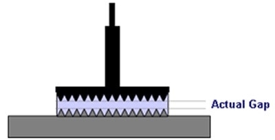
Various approaches are available to counteract wall slip when performing an analysis using a rotational rheometer. Roughened or serrated geometries are highly effective in taking the geometry motion into the bulk of the sample, maximizing the sample-sample contact at the expense of sample-wall interactions (Figure 1). Vanes and splined geometries can also be used for cup and bob systems.

Figure 1. Serrated parallel plates used to minimize slip.
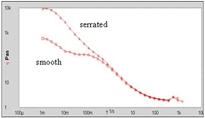
Figure 2 illustrates the effect of slip for a concentrated particle suspension as measured with the help of smooth parallel plates. The apparent 'dog leg' in the flow curve is a well-known characteristic of wall slip. The use of the serrated plates can largely eliminate this 'dog leg.'

Figure 2. Flow curves for a concentrated dispersion with and without serrated plates.
Confirming the presence of wall slip is harder for more subtle occurrences, unless measurements are carried out with smooth and serrated or roughened plates. In many cases a user may not have both geometry types available for a comparison.
In such cases, stress controlled measurements can be performed at different gaps to obtain evidence of slip. If slip exists, then the slip velocity Vs will rely only on the shear stress applied (σ) but not on the gap. Conversely, the difference in velocity across the sample that is used in the shear rate calculation will depend on both the gap and the shear stress. Therefore, the slip velocity and the true shear rate can be calculated using the following equation by keeping the stress (σ) constant and varying the gap (h).

Where, V is the velocity of the upper plate;  is the measured shear rate and Ý is the true shear rate.
To achieve this, the measured shear rate ( ) is plotted against 1/h, which should yield a straight line with gradient 2VS and intercept
 .jpg) .
.
In certain cases, negative values have been noticed for the true shear rate due to gap accuracy, loading errors, and gap dependent material properties. Therefore, working at larger gaps is preferable in order to minimize such errors.

This information has been sourced, reviewed and adapted from materials provided by Malvern Panalytical.
For more information on this source, please visit Malvern Panalytical.