Time of flight mass spectroscopy is a robust analytical tool that works based on a straightforward principle. It involves creating, first, a population of singly-charged ions with a fixed energy, allowing them to travel a fixed distance. Their arrival is then measured using a detector. Their mass can be calculated using the time taken to travel the distance. The obtained mass spectrum consists of a number of peaks corresponding to the mass of the detected ions. The amount of mass that is analyzed can be inferred from the peak height.
Although the ions of the same mass are ideally expected to arrive at the detector at the same instance, in reality, the width of the peaks in a mass spectrum is limited, which governs the potential of the mass spectrometer to separate ions that have similar masses.
This number, which is known as the 'mass resolution' of the instrument, is calculated by comparing the width to the total time of flight. Figure 1 illustrates a peak with a width of 2.2 ns and a flight time of 90.7 µs, leading to a mass resolution of 20,000.
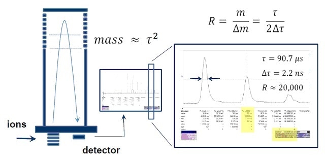
Figure 1. Any travel-time difference for ions of the same mass in a TOF system reduces the mass resolution.
Several ongoing studies are attempting to find ways to improve these machines. Irrespective of the method and scale of improvement, the goal is the same: to reduce the in-system peak width. As illustrated in Figure 1, the mass resolution of the instrument is affected by any factor that increases the measured ion peak width.
Microchannel Plates
In order to detect individual ions and to achieve the required sensitivity, an electron multiplier is used as a detector in all time of flight mass spectrometers. In these devices, the energetic surface is struck by the incoming ion, where emission of at least one secondary electron takes place.
The speed of the secondary electron is increased by an electric field, and the multiplier is struck again, resulting in the emission of multiple electrons. In a microchannel plate (MCP), this process occurs several times in many parallel electron multipliers, generating an output pulse of a million electrons from a single ion.
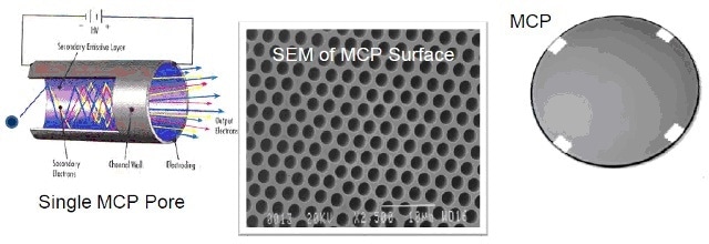
Figure 2. Microchannel plates are parallel arrays of individual electron multipliers with each pore (or channel) having a diameter of the order of microns or tens of microns.
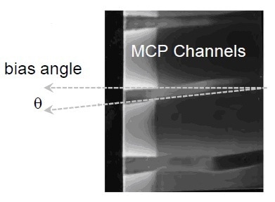
Figure 3. The channels are typically not normal to the input surface of the microchannel plate but instead pitched at a slight angle called the bias angle.
Detector Time Jitter
The following factors lead to the occurrence of a detector time jitter in the MCP:
- The detector has a finite pulse width. The physical dimensions of the multiplier and the electric fields in it govern the pulse width such that MCPs with dimensions in micrometers are generally fast. Moreover, MCPs with smaller pore size are smaller compared to those with larger pores.
- The detector contributes to the width by changing the ion arrival time. Individual ion peaks come under the time of flight peak envelope, and the term jitter comes from this as the pulse jitters to and fro. The flight instrument causes a part of this jitter.
Reducing Detector Time Jitter
The following three points demonstrate how it is possible to reduce the detector time jitter:
- It should be ensured that the detector pulse is fast and that electrons arrive at the anode at the same instance
- The presence of magnetic or electric fields should be avoided to ensure that the flight of the incoming ions is not affected
- It should be made sure that the ions strike a surface that is planar and parallel to the incoming ion packet
Global Flatness
It is vital to ensure that the MCP surface is planar. The flatness of the incoming surface of the MCP is determined by measuring the total focus plane deviation (FPD) with the help of machine vision systems, such as those currently used in the semiconductor industry, which have the ability to measure flatness as low as 0.2 µm.
The global flatness is a single number with units of distance.
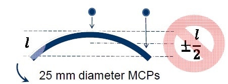
Figure 4. The machine vision system helped measure the absolute flatness as well as determine the shape of the input surface.
Mounting Pad Microchannel Plates
In general, a solid glass border surrounds the field of channels, thereby facilitating a secure mechanical connection to the MCP when it is mounted on the detector hardware. This could result in significant bowing or warping, which is sufficient enough to be detected with the naked eye.
The mounting pad architecture was developed by evenly spacing out four individual mounting pads on the outer edge of the MCP rather than a solid glass border. This prevents warping, thereby ensuring better flatness values.
Hardware Effect on Global Flatness
Various experiments were performed to demonstrate the effect of the detector on the global flatness.
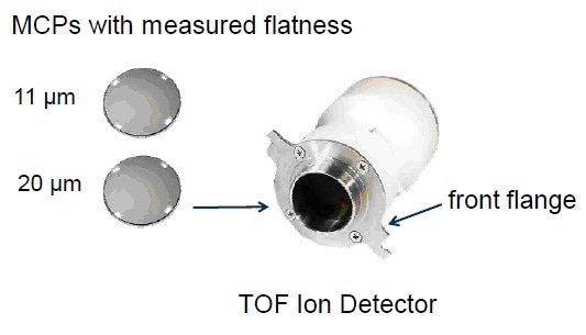
Figure 5. Ion detector assembly with two MCPs to measure the effect of global flatness
Two MCPs of known measured flatness were taken into account. The detector assembly was repeated with the same housing but using eight different hardware units for the front flange, varying the assembler and date of assembly.
Measurement of the flatness of the complete MCP surface (mounted in the detector housing) was recorded. Good hardware was found to enhance the MCP flatness whereas bad hardware was found to degrade it. The circled red dot (Figure 6) illustrates that assembly errors will result in more inferior flatness values than MCPs or similar hardware.
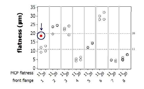
Figure 6. Assembly error has a greater impact on results than the hardware quality.
Time Spread Due to Ion Arrivals
The ion optic modeling program 'Simion' can be used to both model the flight time of the ions to incorporate the ion motion in the MCP channel electric field, and also to ascertain the total time spread based on the ion mass. Figure 7 illustrates the time delay in picoseconds as a function of mass.
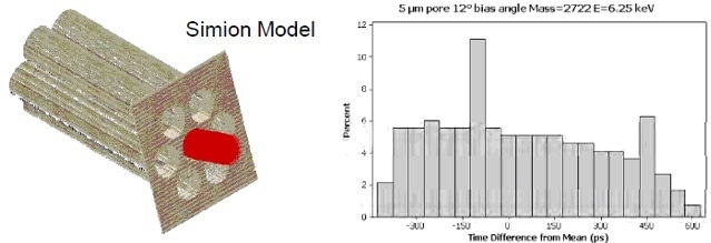
Figure 7. Model of ion motion in the MCP, with the time delay given as a function of mass
Conclusion
The time of flight mass resolution can be optimized by:
- Controlling the MCP global flatness
- Decreasing the MCP pore size
- Increasing the MCP bias angle

This information has been sourced, reviewed and adapted from materials provided by PHOTONIS Technologies S.A.S.
For more information on this source, please visit PHOTONIS Technologies S.A.S.