Cellulose is well known as the principal component of plants. It is also the most plentiful carbohydrate in the world, used as a raw material in textile and paper manufacturing since antiquity. In more recent years, cellulose nanofiber (CNF), with higher functionality achieved by defibrating cellulose to the nano level, has attracted significant attention.
CNF has minimal environmental impacts because it is a plant-derived material. It also possesses a wide range of desirable functions such as a gas barrier property, low linear expansion, and transparency. CNF is lightweight - weighing only a fifth as much as steel - while exhibiting high specific strength between 5 and 8 times stronger than ferrous materials.
The research aimed at the development of composite materials with a combination of high strength and lightweight is currently in progress. Researchers hope that by adding CNF to thermoplastic resins, these new materials will be beneficial in a range of sectors.
One such sector is the automotive industry, where a key goal remains the improvement of fuel efficiency via a reduction in auto body weight. Considering the use conditions of automobiles, it is important that clarity is achieved not only in relation to the static mechanical properties of materials, but also of their fatigue characteristics, impact properties, and thermal characteristics.
This article sees the tensile strength of CNF-reinforced plastic being evaluated at numerous test speeds (strain rates) using a high-speed impact testing machine and a Shimadzu testing machine. Following these tests, the fracture surfaces of the specimens were also observed using an electron probe microanalyzer (EPMA).1
Measurement System
Figure 1 displays the condition of the high-speed tensile test and the static tensile test. An AGS-X table-top type universal testing machine was employed in low-speed tests, while a HITS™-TX high-speed impact testing machine was employed in high-speed tests.
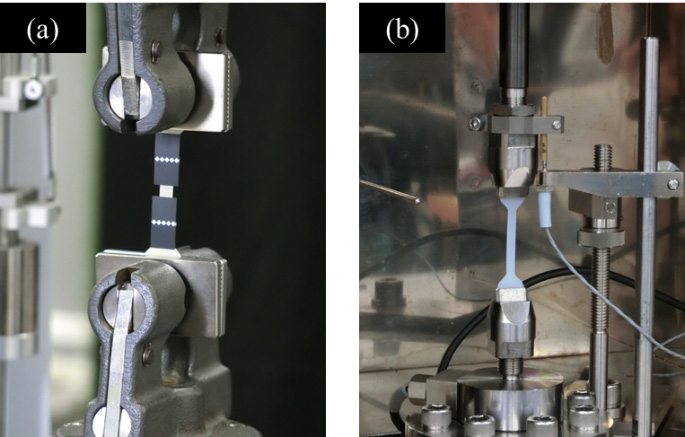
Figure 1. Condition of Tests. (a) Static Tensile Test, (b) High-Speed Tensile Test.
An optical microscope and an EPMA™- 8050G electron probe microanalyzer were utilized in observations of the specimens’ fracture surfaces after the tests. Table 1 illustrates the range of test equipment utilized in this study.
Table 1. Test Equipment.
| . |
. |
. |
| Testing machines |
: |
AGS-X (static tensile tests)
HITS-TX (high-speed tensile tests) |
| Load cell |
: |
1 kN (AGS-X)
2 kN (HITS-TX) |
| Grip |
: |
Pneumatic flat grip (AGS-X)
Grip for plate specimens (HITS-TX) |
| Fracture surface observation |
: |
EPMA-8050G |
Table 2. Test Conditions and Specimen Information.
| . |
. |
. |
| Test speed |
: |
0.0001, 0.001, 0.01, 0.1 /s (AGS-X)
0.1, 1, 10, 100 /s (HITS-TX)
(0.000004 - 4 m/s) |
| Test temperature |
: |
Room temperature |
| Number of tests |
: |
n = 3 |
| Specimens |
: |
HDPE, CNF10%/HDPE |
| Specimen dimensions |
: |
T1 mm × W5 mm, parallel part 40 mm |
Measurement Results
Two types of specimens were prepared. One type used high-density polyethylene (HDPE) while the other used HDPE reinforced with 10% CNF (CNF10%/HDPE). Table 2 displays the full test conditions and related specimen information.
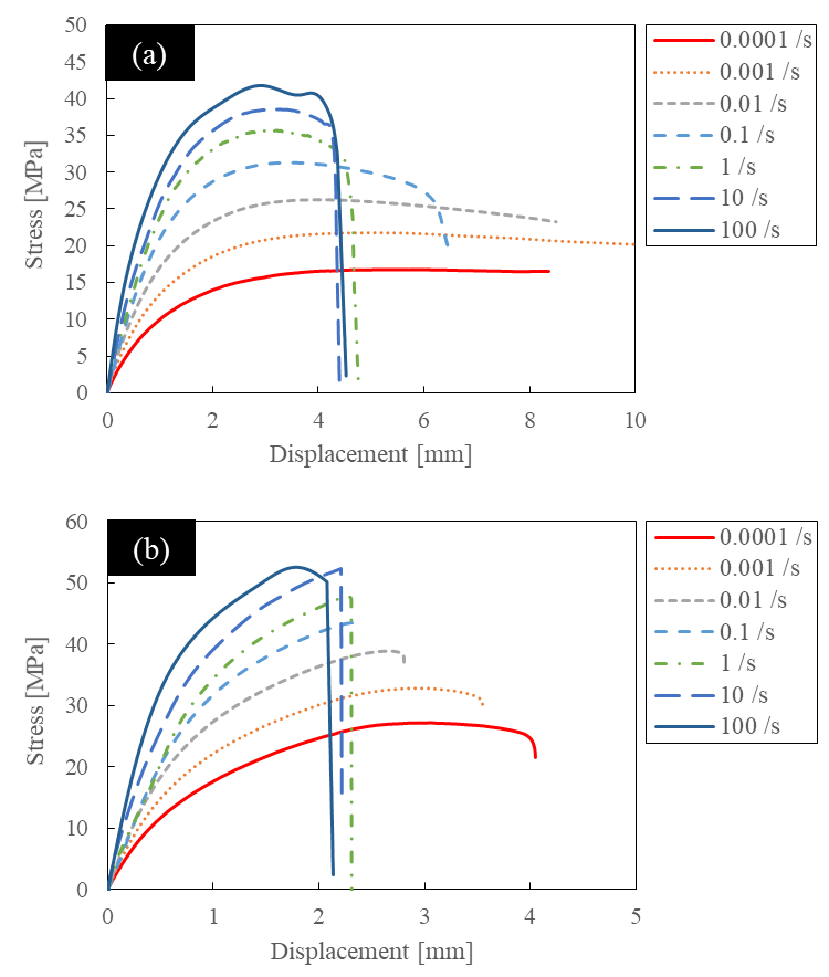
Figure 2. Stress-Displacement Curves. (a) HDPE, (b) CNF10%/HDPE.
Figure 2 gives examples of the stress-displacement curves of both the HDPE and CNF10%/HDPE at different strain rates. As can be seen in Figure 2, both materials demonstrated lower tensile strength as the test speed decreased while demonstrating higher tensile strength at higher test speeds. Additionally, the slopes of the stress-displacement curves were also seen to become larger as test speed increased.
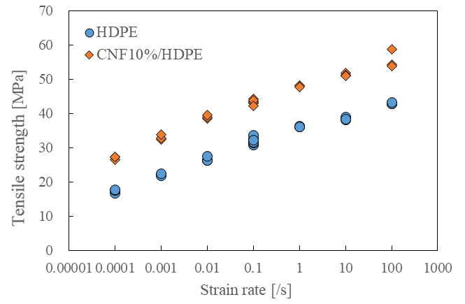
Figure 3. Relationship Between Strain Rate and Tensile Strength.
Figure 3 displays the relationship between the tensile strength and strain rate. The results in Figure 3 show that CNF10%/HDPE exhibited larger tensile strength under every strain rate condition. The tensile strength was also found to increase at higher test speeds.
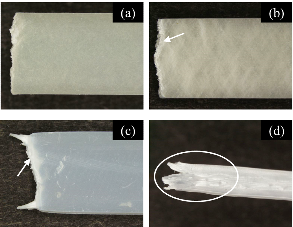
Figure 4. Images of Lateral Surfaces of Specimens after Test. (a) CNF10%/HDPE, 100 /s, (b) CNF10%/HDPE, 0.0001 /s, (c) HDPE, 100 /s, (d) HDPE, 0.0001 /s.
Figure 4 displays images of the specimens’ lateral surfaces after the test was photographed with the optical microscope. The left side of the images shows the fracture surface. Figures 4(b), (c), and (d) indicate that whitening has taken place around the fracture surfaces.
These images indicate that the fracture mode is a ductile fracture. In Figure 4(b), a pale diagonal stripe has appeared, but, because Figure 4(a) reveals practically no traces of whitening, it is believed that brittle fracture took place in this specimen.
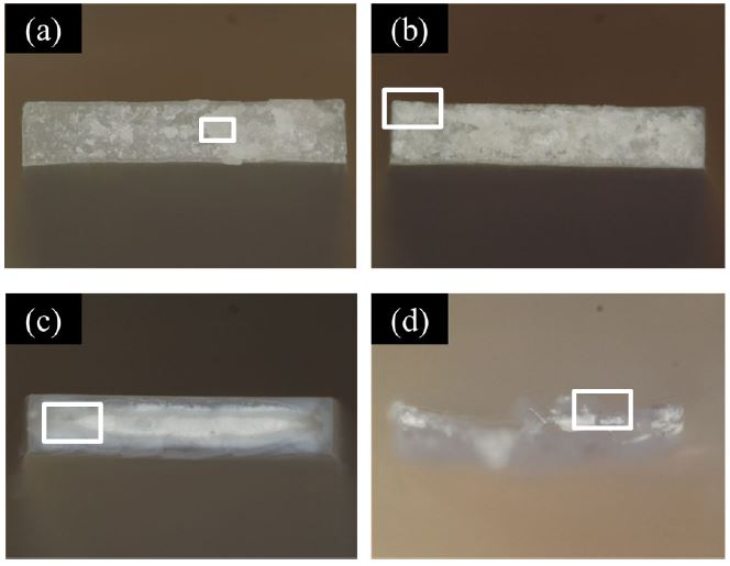
Figure 5. Images of Fracture Surfaces of Specimens after Test. (a) CNF10%/HDPE, 100 /s, (b) CNF10%/HDPE, 0.0001 /s, (c) HDPE, 100 /s, (d) HDPE, 0.0001 /s.
Figure 5 displays images of the fracture surfaces after the test was photographed using the optical microscope. Figure 6 reveals the EPMA images of the parts defined by the white frames in Figure 5. Meanwhile, Figure 6(a) shows a condition whereby fractures had occurred in fibers in which defibration had not progressed.
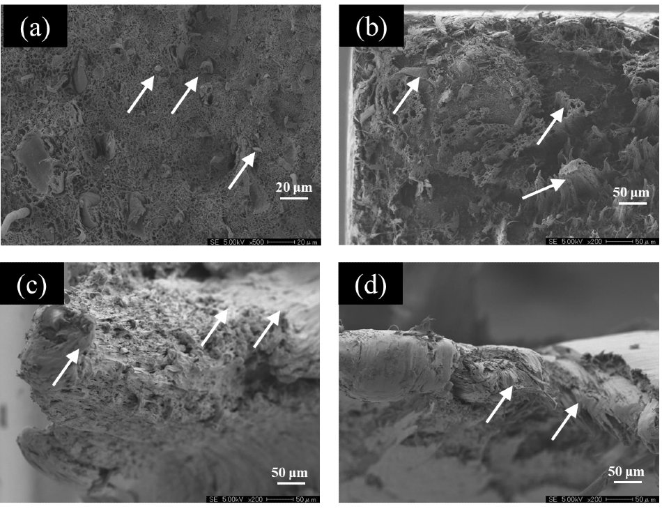
Figure 6. EPMA Observation Images of Fracture Surfaces. (a) CNF10%/HDPE, 100 /s, (b) CNF10%/HDPE, 0.0001 /s, (c) HDPE, 100 /s, (d) HDPE, 0.0001 /s.
Fracture of the fibers cannot be seen in Figure 6(b), but a condition of ductile elongation was observed in the resin which contained CNF. The image in Figure 6(c) is the result of an observation of the most elongated part seen in Figure 5. Ductile elongation of the resin was exhibited in this figure, while the elongation of the resin could also be seen in Figure 6(d).
Conclusion
In this study, a high-speed tensile test of CNF10%/HDPE and HDPE was performed. The results confirmed that tensile strength altered depending on test speed. Additionally, fracture surfaces after the tests were observed, explaining the fact that differing fracture surfaces had been found.
The HITS-TX and AGS-X allow a wide range of strain rates to be defined as test conditions, meaning that these testing machines are highly suited for evaluation of the strain rate dependency of resins.
References and Further Reading
- Fumiaki Yano, Yuki Kamei, Takeshi Senba, and Kazuo Kitagawa, Abstracts of the Symposium on Polymer Processing ’19 (2019)

This information has been sourced, reviewed and adapted from materials provided by Shimadzu Scientific Instruments.
For more information on this source, please visit Shimadzu Scientific Instruments.