The most common solders are tin-lead alloys with low melting points. Their high-quality cross-section for SEM and EPMA and thin films for TEM are difficult to be prepared using ion beam milling. This is because damage to the interface between the thin-rich and lead-rich phase is easily damaged by the temperature increase due to the ion beam irradiation.
In recent times, it has been possible to prepare high quality undamaged cross-sectional phases via an installation of an Ion Slicer to the broad Ar ion beam milling instrument (IS)1, with a specimen cooling unit that chills the specimen down to -120 ℃. Figure 1 illustrates a standard of the traditional IS in which the Ar ion source, the specimen, and the shielding belt and are arranged as shown.
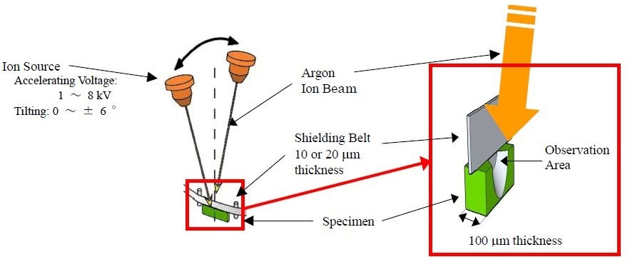
Figure1. A schematic illustration of the principle of the Ion Slicer.
The specimen for the IS has to be pre-prepared as a small thin plate with a size of 2.8 mm (head) x 1.0 mm (width) x 0.1 mm (thickness). Once the pre-prepared plate is carefully positioned in the IS, the shielding belt automatically lowers specifically onto the specimen plate. The accelerated voltage of the Ar ion beam can be selected between 1 and 8 kV.
The automated Ar ion beam is constantly and automatically rocked with an angle up to ±6 degrees throughout specimen milling: this can also be performed without rocking. The broad Ar ion beam mills both sides of the sections where the shielding belt does not conceal the specimen. As the milling takes place, a thin section is made beneath the shielding belt. Therefore, free from the rocking of the Ar ion beam, the specimen can be milled to the same thickness as the shielding belt.
Two variations of the shielding belts are available commercially with 10 and 20 μm in thickness. The thinner of the two belts is used for the preparation of thin foil, while the thicker one is utilized for the preparation of the cross-section. Figure 2 exhibits the positioning of the specimen cooling unit. - The IS equipped with this specimen cooling unit is called Cryo IS. When the temperature of the specimen has to be reduced throughout milling, the cooling conductor is connected to the specimen stage, as illustrated in Figure 2-1.
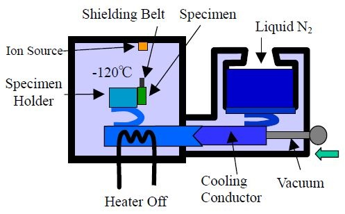
Figure 2-1. Cooling mechanism during etching.
Cooling the specimen to - 120 ℃ takes about 1 hour. Prior to removal of the specimen subsequent to milling, the cooling conductor is detached from the stage, and then the milled specimen is then brought back room temperature by the heater as demonstrated in Figure 2-2. This process takes around 30 minutes (to bring the specimen to room temperature), then, the specimen chamber is opened for the specimen exchange. These operations can be performed with liquid nitrogen confined to the dewar.
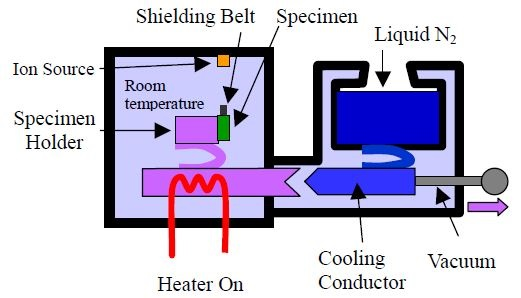
Figure 2-2. Cooling mechanism during specimen exchange.
Figures 3-1 and 3-2 exhibit backscattered electron images (BSEIs) of a cross-sectional plane, prepared with the IS, at the accelerating voltage of the Ar ion beam of 4 kV of a milling period of about of 4 hours. The tin-rich phase is seen as a dark contrast, while the lead-rich phase is shown as a white contrast. It is obvious that when the cross-section is prepared with a cooling of the specimen there is an increase in quality than when specimen cooling is not performed: several artifacts, such as voids encircling the lead-rich phase are seen in the latter section.
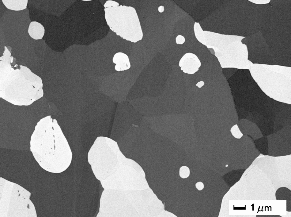
Figure 3-1. A BSEI of a cross-sectional plane with the specimen cooling.
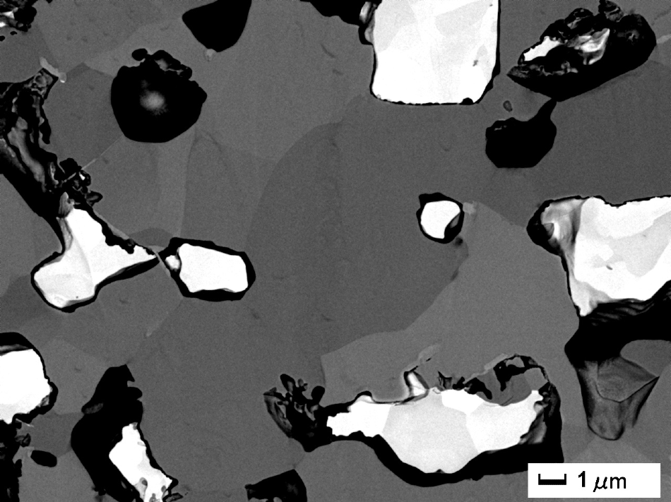
Figure 3-2. A BSEI of a cross-sectional plane without the specimen cooling.
The usefulness of the specimen cooling unit is established for the preparation of high-quality cross-sections of alloys with low melting points. This unit is also appropriate for the preparation for superior cross-sections for SEM and EPMA, and premium quality thin films for TEM, of specimens susceptible to heating due to ion milling.
Acknowledgments
Produced from materials originally authored by H. Matsushima*, Y. Nakajima *, N. Erdman** and K. Kawauchi* from
*: SEM Application Group, JEOL Ltd. Musashino 3-1-2, Akishima, Tokyo, 196-8558 JAPAN
**: JEOL USA, Inc. 11 Dearborn Road Peabody, MA 01960.
References and Further Reading
- A. Yasuhara: JEOL News, 40 (1), 46-49 (2005)

This information has been sourced, reviewed and adapted from materials provided by JEOL USA, Inc.
For more information on this source, please visit JEOL USA, Inc.