Sponsored by MerckJan 4 2021
Graphene is a one-atomic-layer thick two-dimensional material comprised of carbon atoms organized in a honeycomb composition. Its interesting optical, electrical and mechanical attributes created a lot of attention from the physics, chemistry and materials science fields.1–3 The recently detected attributes lead to applications in transparent conductive films, composites, electronic and opto-electronic devices, actuators, sensors, amongst others.
Graphene nanoribbons (GNRs) are narrow strips of graphene. The quasi-one-dimensional disposition of GNRs causes further benefits over graphene sheets, the more commonly known two-dimensional counterpart to GNRs. For instance, the high aspect ratio of GNRs substantially decreases the percolation ceiling in conductive films and polymer composites and makes them appropriate for spinning fiber from their liquid crystalline configuration.
Synthesis Techniques
The composition and physical attributes of GNRs differ substantially based on the synthesis technique—a single term for all GNRs can produce uncertainty in non-experts due to the subsequent fundamental distinction between varying kinds of GNRs. Currently, there are three key methods for the fabrication of GNRs: 1) cutting from graphene employing lithography; 2) bottom-up synthesis from polycyclic molecules; 3) unzipping of carbon nanotubes (CNTs). Despite this, GNRs manufactured employing those three techniques are significantly different and do not have a lot in common.
Lithography
This method generates single-layer GNRs on a substrate surface. The amount of articles on this technique is considerable. The employment of lithographically generated GNRs is restricted to applications in which GNRs lie flat on a surface. Bulk quantities cannot be manufactured employing lithographic techniques. Furthermore, because of fundamental restrictions in the lateral resolution of lithography-based techniques, lithographically generated GNRs have rough edges.4–6 Although this technique generates extremely accurate and very narrow GNR, the subsequent uncontrolled jagged edges create a challenge in monitoring the electronic properties of the resultant materials.
Bottom-Up
The bottom-up fabrication of GNRs entails multi-step organic synthesis centered on cyclization of pre-synthesized polymer chains. This technique permits the formation of extremely narrow ribbons with atomically accurate edge alignment.7–9 This kind of GNRs could just be prepared on the surface of a substrate until recently,7,8 reducing the possibility for bulk manufacture. Although these ribbons have been synthesized recently on a scale of hundreds of milligrams,9 it is challenging to gauge their actual applications in the near future. While the extreme precision and narrow size allocation stemming from the bottom-up synthesis of GNRs may produce future advantages, there are no ready-to-use methods currently to further process these tiny structures.
Unzipping
The third method of the fabrication of GNRs is founded on the longitudinal opening, or unzipping, of multi-walled carbon nanotubes (MWCNTs).10,11 The reported methods differ, but the majority of them are solution-based processes. The key benefit of this technique over the previous two is the possibility of mass production on the kilogram scale. Substantially minimized cost is a further benefit. Additionally, due to the number of recent publications, it is expected that these CNT-derived GNRs will be the first to discover actual applications. This article will examine the multiple aspects of GNRs created by the unzipping of carbon nanotubes in addition to their current and developing applications.
Production of GNRs by Unzipping of Carbon Nanotubes
The Tour group initially established the technique employed to create GNRs by the longitudinal splitting of carbon nanotubes using potassium (K) vapor and then soon after in solution employing sodium-potassium alloy (Na/K)10 (Figure 1).
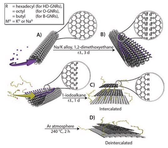
Figure 1. Scheme for unzipping and functionalization of GNRs: (A) intercalation of potassium between the walls of MWCNTs; (B) splitting process of MWCNTs and formation of GNRs with active carboanionic edges (M = K or Na); (C) in situ functionalization and intercalation of GNRs with alkyl groups; and (D) deintercalation of functionalized GNRs. Reprinted with permission from ACS Nano, 2012, 6, 4231–4240. Copyright 2012 American Chemical Society.10
MWCNTs are unzipped via intercalation of the K/Na alloy between the nanotube walls in a 1,2-dimethoxyethane (DME) solvent, which can be seen in Figure 1A. This lattice expansion causes ample stress to longitudinally break the nanotube walls. The carbon atoms at the newly formed edges are diminished to their extremely reactive carbanionic form (Figure 1B), making them incredibly vulnerable to electrophilic attack.
If the transitional product (Figure 1B) is quenched with methanol, followed by aqueous washing, the metal cations on the edges are substituted with protons. This results in H-terminated GNRs (Prod. No. 797774) or GNRs. Figure 2 displays MWCNTs completely unzipped following treatment. These GNRs, though, are not entirely flat because of van der Waal’s interaction across the nanotube walls.
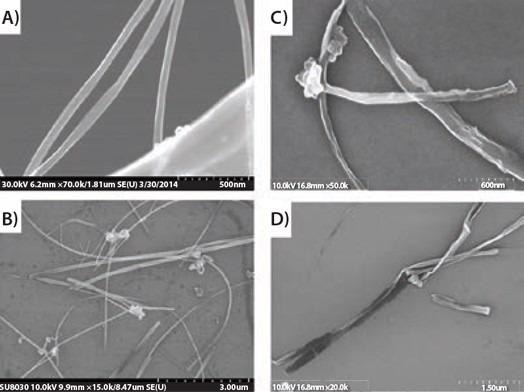
Figure 2. SEM images of (A) and (B) MWCNTs and (C) and (D) fully unzipped MWCNTs. Image Credit: Merck
The GNRs can be totally flattened and partly exfoliated by bath sonication in chlorosulfonic acid.11 The electrical conductivity of the flattened 3.5 to 5 nm thick GNR stacks, containing 10 to 14 layers, is in the span of 70,000 to 95,000 S/m.11 These values are similar to the data reported for different graphitic structures.
To formulate alkylated GNRs (alk-GNRs) (HD-GNRs when R=hexadecyl, Prod. No. 797766), the intermediate product is subjected to 1-halo-alkanes (Figure 1C). Intercalated potassium is effectively substituted by haloalkanes that primarily functionalize the edges (and, to some extent, the basal planes) and behave as intercalants in the subsequent alk-GNRs. The alk-GNRs carrying long alkyl chains are well-dispersible in organic solvents like ketones, alcohols, alkanes and ethers (Figure 3). Especially stable dispersions are created in chloroform or chlorobenzene.
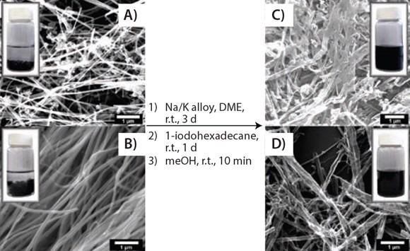
Figure 3. Solubility test. SEM images showing the splitting and functionalizing of commercially available MWCNTs and the photographic difference in solubility between functionalized GNRs and pristine MWCNTs: (A) and (B) two different types of pristine MWNTs and a 0.1 mg/mL suspension in chloroform; (C) and (D) hexadecylated (HD)-GNRs and a 0.1 mg/mL stable dispersion in chloroform. Reprinted with permission from ACS Nano, 2012, 6, 4231–4240. Copyright 2012 American Chemical Society.10
Raman spectroscopy (Figure 4) has been established as an efficient and non-destructive technique for the characterization of graphitic carbon nanostructures. The key Raman signals in the spectra of any kind of graphitic carbon are the G-band at ~1,680 cm-1 and the 2D-band at ~2,700 cm-1. The D-band at ~1,360 cm-1 is triggered by flaws functioning as photon scattering centers and it is symptomatic of the quality of the graphitic structure. As such, evolution of the D-band throughout unzipping and functionalization processes provides useful information about the nature of as-prepared GNRs.
The Raman spectrum of MWCNTs includes only weak D-band signals, implying high crystallinity of the parent MWCNTs. In the spectrum of as-produced protonated GNRs, the D-band concentration substantially rises. This is credited to the carbon atoms on ribbon edges, which serve as photon scattering centers.
Following alkylation, the D-band intensity rises even more, suggesting a rise in the defect density. This is attributed to some covalent functionalization of the GNRs’ basal planes. Basal plane alkylation transforms the sp2 carbon atom to the sp3 carbon atom, as such, establishing a defect in the graphene plane, which, apart from this, is perfect. The G/2D ratio for alk-GNRs relates to that of a single layer graphene. This implies the partition of GNRs produced by intercalation of alkyl chains throughout the GNRs.
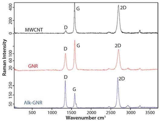
Figure 4. Raman spectra for MWCNTs, GNRs and alk-GNRs. Image Credit: Merck
Potential Applications of GNRs
Both H-terminated GNRs (Prod. No. 797774) and alkylated GNRs (Prod. No. 797766) have a wide variety of possible functions. The most obvious is the integration of GNRs in polymer hosts for the production of new composite materials. GNRs possess the identical high aspect ratio as their parent MWCNTs, but variations in their nanostructure create distinctive and unforeseen outcomes. For instance, the integration of GNRs into a dielectric polymer host significantly alters its electric properties12,13 in a way substantially distinct from that attained by integration of MWCNTs.
The most interesting outcome is that GNR-containing polymer composites have surprisingly low loss (<0.02) at fairly high permittivity values (Figure 5). This is critical as the shrinking of electronic components needs materials with high permittivity and low loss in the radio and low microwave frequency region. In the high frequency microwave region, low loss is vital for antennas and additional military functions.
By altering the kind and content of GNRs, the loss and permittivity of composites may be adjusted to attractive values over a broad range. The dielectric constant may be adjusted from modest to very high (>1,000) values, while the consequent loss tangent can range from ultralow (<0.02) to high (~1.0).13

Figure 5. Dielectric properties of the GNR/NuSil (silicon elastomer) composites. (A) Real permittivity, (B) imaginary permittivity, and (C) loss tangent of pure NuSil (black), MWCNT/NuSil (blue), and GNR/NuSil (red) composites containing 0.5 wt % incorporated conductive filler. Reprinted with permission from ACS Appl. Mat. Interf. 3, 4657-4661 (2011). Copyright 2011 American Chemical Society.12
A further encouraging application of GNRs is as electrode material for batteries and supercapacitors. In one instance,14 a distinct hierarchical structure composite of graphene-wrapped MnO2-GNRs (GMG) was effectively conceived and synthesized (Figures 6 and 7). In this composite, graphene flakes closely sandwiched nanosized MnO2 that grew directly on the GNRs.
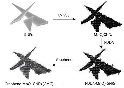
Figure 6. Illustration of the synthesis of the graphene-wrapped MnO2-GNRs (GMG) composite. Reprinted with permission from Adv. Mater. 2013, 25, 6298–6302. Copyright 2013 John Wiley and Sons.14
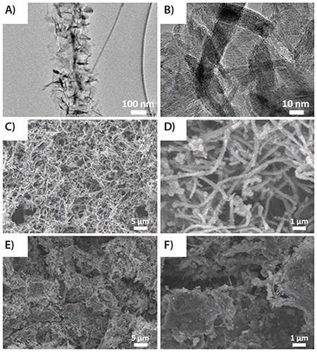
Figure 7. (A) and (B) TEM images of MnO2-GNRs (MG); (C) and (D) SEM images of MG; and (E) and (F) GMG. Reprinted with permission from Adv. Mater. 2013, 25, 6298–6302. Copyright 2013 John Wiley and Sons.14
The synthesis of the GMG composite has created an efficient component to enhance the electrochemical solidity of the electrode materials for lithium-ion batteries.
Electrochemical experiments show that the GMG displays improved precise capacity and enhanced cycling strength as anode materials contrasted to MnO2-graphene or pure MnO2 due to the synergic effect between the graphene, GNRs and MnO2. These traits aided the accomplishment of stable capacity at multiple current densities. For instance, the value of a particular capacity grew to 890 mAh/g at 180 cycles from 672 mAh/g at two cycles in the existing density of 0.1 A/g. The rate performance shows that the GMG electrode stayed stable following expanded rate cycles. For GMG, in the initial five cycles, the exact capacity reduced as was seen with MG.
Following five cycles, the value of GMG discharge capability reduced from 571 mAh/g at six cycles to 465 mAh/g at 20 cycles, but then improved to 648 mAh/g at 170 cycles. Even following 250 cycles, the GMG still retained a particular capacity of 612 mAh/g. The Coulombic effectiveness of GMG was retained at over 99%, not including the initial several cycles.
In a further study,15 GNRs were employed to construct a nanocomposite material of polyaniline (PANI) and GNRs (Figure 8). GNRs were chosen as a template on which PANI nanorods were cultivated. A nanocomposite of PANI-GNRs was formulated by the in-situ polymerization of aniline in the company of GNRs. In this composite, GNRs function as the substrate to cultivate the PANI nanorods and enhance the electrical conductivity of the composite, but additionally, they enhance the efficient application of PANI and improve the mechanical property of the composite.
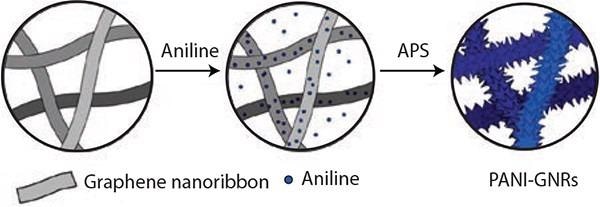
Figure 8. Illustration of the synthesis of the PANI-GNRs composite with PANI polymerized directly on the GNRs using APS (ammonium persulfate). Reprinted with permission from ACS Appl. Mat. Interf. 2013, 5, 6622–6627. Copyright 2013 American Chemical Society.15
The resultant composite has a large capacitance of 340 F/g and stable cycling performance with 90% capacitance preservation throughout 4,200 cycles. The high performance of the composite comes from the synergistic mixture of electrically conductive GNRs and extremely capacitive PANI.
As an additional possible application, alk-GNRs were employed in polymer composites to decrease the permeability of gases.16 A thermoplastic polyurethane (TPU) composite film including alk-GNRs was created by solution casting. The HD-GNRs (Prod. No. 797766) were well dispersed throughout the polyurethane matrix, causing the phase partition of the TPU. Nitrogen gas effective diffusivity of TPU was reduced by three orders of magnitude with just 0.5 wt % alk-GNRs (Figure 9).
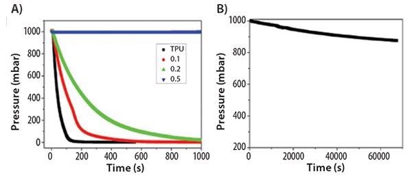
Figure 9. (A) Pressure drop of TPU and TPU/HD-GNRs films with respect to time. (B) Pressure drop of TPU/0.5 wt % HD-GNRs composite film over a longer time period. Reprinted with permission from ACS Appl. Mat. Interf. 2013, 7, 10380–10386. Copyright 2013 American Chemical Society.16
The inclusion of alk-GNRs additionally enhanced the mechanical attributes of the composite films, as projected by the phase separation and signaled by tensile tests and dynamic mechanical analyses. The enhanced attributes of the composite film may result in possible applications in food packaging and lightweight mobile gas storage containers. As a display of their ability to inhibit gas permeation, the comparison of efficacies in Table 1 can be seen in Figure 9.
Table 1. Comparison of different additives to polymer composites for their role as a gas barrier. Source: Merck
| Barrier Material |
Gas Permeation |
| GO17 (Prod. No. 763705 , etc) |
80× decrease at 3 wt % filler |
| Nanoclay18 (Prod. No. 682608 , etc.) |
14× decrease at 28 wt % filler |
| HD-GNRs (Prod. No. 797766 ) |
1,000× decrease at 0.5 wt % filler |
Conclusion
Both GNRs and alk-GNRs have an excellent capacity for many applications. At present, the most encouraging applications are polymer composites and electrode materials for energy storage. It is anticipated that these small structures will earn further attention as they develop into being more readily accessible for researchers and their distinctive attributes become more widely realized.
Acknowledgments
Produced from materials originally authored by Ayrat M. Dimiev and James M. Tour.
References and Further Reading
- Geim, A. K.; Novoselov, K. S. The rise of graphene. Nature Materials 2007, 6, 183–191.
- Geim, A. K. Graphene: status and prospects. Science 2009, 324, 1530–1534.
- Novoselov, K. S.; Fal’ko, V. I.; Colombo, L.; Gellert, P. R.; Schwab, M. G.; Kim, K. A. Roadmap for graphene. Nature 2012, 490, 192−200.
- Han, M. Y.; Özyilmaz, B.; Zhang, Y.; Kim, P. Energy band-gap engineering of graphene nanoribbons. Phys. Rev. Lett. 2007, 98, 206805.
- Wang, X.; Dai, H. Etching and narrowing of graphene from the edges. Nature Chem. 2010, 2, 661–665.
- Abramova, V.; Slesarev, A.; Tour, J. M. Meniscus-Mask Lithography for Narrow Graphene nanoribbons. ACS Nano 2013, 7, 6894–6898.
- Long, C.; Hernandez, Y.; Feng, X.; Müllen, K. From nanographene and graphene nanoribbons to sheets: chemical synthesis. Angew. Chem. Int. Ed. 2012, 51, 7640–7654.
- Cai, J.; Ruffieux, P.; Jaafar, R.; Bieri, M.; Braun, T.; Bankenburg, S.; Muoth, M.; Seitsonen, A. P.; Saleh, M.; Feng, X.; Müllen, K.; Fasel. R. Atomically precise bottom-up fabrication of graphene nanoribbons. Nature 2010, 466, 470–473.
- Vo, T. H.; Shekhirev, M.; Kunkel, D. A.; Morton, M. D.; Berglund, E.; Kong, L.; Wilson, P. M.; Dowben, P. A.; Enders, A.; Sinitskii, A. Large-scale solution synthesis of narrow graphene nanoribbons. Nature Comm. 2014, DOI: 10.1038/ncomms4189.
- Genorio, B.; Lu, W.; Dimiev, A. M.; Zhu, Y.; Raji, A-R. O.; Novosel, B.; Alemany, L. B.; Tour, J. M. In situ intercalation replacement and selective functionalization of graphene nanoribbon stacks. ACS Nano 2012, 6, 4231–4240.
- Kosynkin, D. V.; Lu, W.; Sinitskii, A.; Pera, G.; Sun, Z.; Tour, J. M. Highly conductive graphene nanoribbons by longitudinal splitting of carbon nanotubes by potassium vapor. ACS Nano 2011, 5 (2), 968–974.
- Dimiev, A.; Lu, W.; Zeller, K.; Crowgey, B.; Kempel, L. C.; Tour, J. M. Low Loss, High Permittivity Composites Made from Graphene Nanoribbons. ACS Appl. Mat. Interfaces. 2011, 3, 4657–4661.
- Dimiev, A. M.; Zakhidov, D.; Genorio, B.; Oladimeji, K.; Crowgey, B.; Rothwell, E. J.; Kempel, L. C.; Tour, J. M. Permittivity of dielectric composite materials comprising graphene nanoribbons, The effect of nanostructure. ACS Appl. Mater. Interfaces 2013, 5, 7567–7573.
- Li, L.; Raji, A-R. O.; Tour, J. M. Graphene-Wrapped MnO2-Graphene Nanoribbons as Anode Materials for high performance lithium batteries. Adv. Mater. 2013, 25, 6298–6302.
- Li, L. et al. nanocomposite of polyaniline nanorods grown on graphene nanoribbons for highly capacitive pseudocapacitors. ACS Appl. Mat. Interfaces. 2013, 5, 6622–6627.
- Xiang, C. et al. Functionalized low defect graphene nanoribbons and polyurethane film composite for improved gas barrier and mechanical performances. ACS Nano 2013, 7, 10380–10386.
- Kim, M.; Miura, Y.; Macosko, C. W. Graphene/polyurethane nanocomposites for improved gasbarrier and electrical conductivity. Chem. Mater. 2010, 22, 3441–3450.
- Herrera-Alonso, J.; Marand, E.; Little, J. C.; Cox, S. S. Transport properties in polyurethane/clay nanocomposites as barrier materials: Effect of processing conditions. Membr. Sci. 2009, 337, 208–214

This information has been sourced, reviewed and adapted from materials provided by Merck.
For more information on this source, please visit Merck.