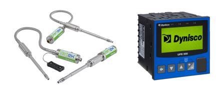
Dynisco pressure sensors have been used around the world and for many different applications for over 60 years.
Dynisco holds the original patent for the melt pressure sensor used in extrusion, and by working side by side with our end users to meet the ever-changing demands of the plastics market has remained the world class industry leader in this technology.
This article will explore the relationship between the dedicated indication device or controller and a pressure sensor, specifically in situations where it appears the pressure reading is not reading correctly and may be causing issues with the process.

Image Credit: Dynisco
The first consideration for the instrumentation is its current length of operation. Unless someone has inadvertently changed parameter settings or the sensor has been damaged, existing installations rarely exhibit pressure errors.
The recommendation for new installations is to follow the instructions for both the instrument and the sensor to confirm that the correct parameters are being met.
The information below will help troubleshoot errors in pressure for either situation.
Check Parameter Settings on the Instrument
The pressure sensor output type should match the pressure range and signal input type. The Dynisco model PT462E-10M-6/18 has an output of 0-33.3 mV based on the pressure range of 0-10,000 psi (10M), for example, meaning that the indication device should be set to accept the input of 0-33.3 mV=0-10,000 psi.
Subsequently, the full pressure range of the sensor will be the basis for all additional parameters such as retransmission outputs and alarms.
Setting the input range to a lower value than the sensor is rated for is not recommended, because this will result in a pressure reading error. This is also the case for setting the input range of the instrument to higher than the pressure transducer’s rating.
Below are two example scenarios to help explain the mathematics of the sensor output and the way the instrument reads the signal input.
Scenario 1: The input range is set to 5,000 psi on the indication device, but the sensor being used has a range of 7,500 psi, and an output 0-33.3mV. Based on the range of 5,000 psi, the indication device interprets the signal range as 150.15 psi/ 1mV (5000/33.3=150.15) resulting in the instrument displaying a lower pressure than what is being seen by the sensor because there is an output of 225.23 psi/ 1mV (7500/33.3=225.23).
The sensor reading 2500 psi in real pressure would have an output of 11.1mV (225.23 x 11.1= 2500) where the instrument will display 1,667, psi due to the lower input setting of 0-5,000 (150.15 x 11.1 = 1,667).
Scenario 2: The input range is set to 10,000 psi on the indication device but the sensor being used has a range of 5,000 psi, and an output 0-33.3mV.
Based on the range of 10,000 psi, the indication device interprets the signal range as 300.3 psi/ 1mV (10,000/33.3=300.3) meaning that the instrument will display a higher pressure than what is being seen by the sensor due to the fact there is an output of 150.15 psi/ 1mV (5000/33.3=150.15)
The sensor reading 3000 psi in real pressure would have an output of 19.98 mV (150.15 x 19.98 = 3000) where the instrument will display 6,000 psi due to the higher input setting of 0-10,000 (300.3 X 19.98= 6,000).
A person could assume the expected signal output against a known pressure (or common pressure of the process) if there is a safe way to check the signal outputs from the pressure sensor at the instrument terminals.
The signal output could be observed against the pressure error through use of a multimeter in order to determine if the instrument has a scaling issue or if the senor output actually has a problem.
In cases where the sensor is indeed the problem, the recommendation would be to check the tip surface for any deformation of the diaphragm, or sensing end. If this reveals that there is no visible damage the next step would be to perform a that instrument’s routine calibration.
The recommendation from Dynisco is to calibrate sensors with zero pressure applied and at operating temperature. In cases where sensor calibration fails to resolve the issue, the next recommended step would be to return the sensor to Dynisco for evaluation.
This can be done by contacting the customer service department and obtaining a return authorization along with instructions for the actual return.
Dynisco manufactures sensors and instrumentation that will last for years provided they are maintained properly, designed to be used in plastic processing environments.

This information has been sourced, reviewed and adapted from materials provided by Dynisco.
For more information on this source, please visit Dynisco.