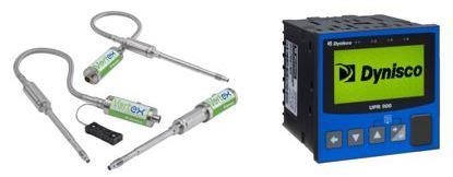
Dynisco’s pressure sensors have been used in a range of applications around the world for more than 60 years.
Dynisco is the original patent holder for the melt pressure sensor employed in extrusion, and the company has maintained its position as an industry leader in this innovative technology, working in partnership with end users to address the ever increasing demands of the plastics market.
This article explores the complex relationship between a pressure sensor and its dedicated controller or indication device. It will specifically examine cases where the pressure sensor does not appear to be reading correctly, leading to issues with the process.

Image Credit: Dynisco
Should this issue arise, initial consideration should be given to the instrumentation itself, particularly the length of time it has been in operation.
Existing installations seldom suffer from pressure errors unless parameter settings have been accidentally altered or the sensor has been damaged in some way. To address pressure errors in new installations, it is advisable to follow the instructions for both the instrument and sensor to ensure that all parameters have been set correctly.
In either situation, the information outlined below will be beneficial in terms of troubleshooting pressure errors.
Instrument Parameter Settings
The signal input type and pressure range must be appropriate to the pressure sensor output type.
For example, Dynisco’s model PT462E-10M-6/18 has an output of 0-33.3 mV based on the pressure range of 0-10000 psi (10M). This means that the indication device must be programmed to accept the input of 0-33.3 mV=0-10000 psi, with every additional parameter (for example, retransmission outputs or alarms) defined based on the sensor’s full pressure range.
It is not advisable to set the input range to a lower value than that of the sensor rating because this will result in pressure reading errors. Similarly, the input range of the instrument should not be set higher than the pressure transducer’s rating.
Understanding Sensor Mathematics
The sensor output works according to specific mathematical principles, and the instrument reads the signal input in a highly specific way. The scenarios outlined below explain these modes of operation using examples.
Scenario 1
If the input range is set to 5000 psi on the indication device despite the sensor in use used having a range of 7500 psi and an output of 0-33.3 mV, the range (5000 psi) will prompt the indication device to interpret the signal range as 150.15 psi/1 mV (5000 / 33.3 = 150.15).
The instrument will therefore display a lower pressure than the pressure determined by the sensor because there is an output of 225.23 psi/1 mV (7500 / 33.3 = 225.23).
A sensor reading of 2500 psi in real pressure would result in an output of 11.1 mV (225.23 x 11.1= 2500). This would cause the instrument to display 1667 psi due to the lower input setting of 0-5000 (150.15 x 11.1 = 1667).
Scenario 2
If the input range is set to 10000 psi on the indication device despite the sensor in use having a range of 5000 psi and an output 0-33.3 mV, the range (10000 psi) will prompt the indication device to interpret the signal range as 300.3 psi/1 mV (10,000/33.3=300.3).
The instrument will therefore display a higher pressure than the pressure determined by the sensor because there is an output of 150.15 psi/1 mV (5000/33.3=150.15).
A sensor reading of 3000 psi in real pressure would result in an output of 19.98 mV (150.15 x 19.98 = 3000). This would cause the instrument to display 6000 psi due to the higher input setting of 0-10000 (300.3 x 19.98 = 6000).
Resolving the Issue
Should there be a safe means of checking signal outputs from the pressure sensor at the instrument terminals, the expected signal output could be verified against a common process pressure or an otherwise known pressure.
In this case, the signal output could be observed using a multimeter and compared with the pressure error in order to ascertain whether there is an issue with the sensor output or a scaling issue with the instrument itself.
Should it be determined that the sensor is the problem, it is advisable to inspect the tip surface to look for deformation of the diaphragm (sensing end). If no damage is visible, a full instrument calibration routine should be performed.
Dynisco recommends that its sensors are calibrated with zero pressure applied and at operating temperature. If calibrating the sensor does not solve the problem, it may be necessary to return the sensor to the manufacture for further evaluation.
Provided they are appropriately used and maintained, Dynisco’s range of sensors and instrumentation can be employed in plastic processing environments for many years.
Acknowledgments
Produced from materials originally authored by David Azevedo from Dynisco.

This information has been sourced, reviewed and adapted from materials provided by Dynisco.
For more information on this source, please visit Dynisco.