Sponsored by CSEMReviewed by Mychealla RiceJul 12 2022
CSEM has produced Single Mirror Tile demonstrators (SMT) as part of the PULSAR H2020 Project, which includes a positioning mechanism that can modify the position of the hexagonal mirror to compensate for imperfections caused by the in-orbit robotic assembly.
The mirror position is controlled by this mechanism with three degrees of freedom (piston translation and tip and tilt rotations). CSEM’s vast experience in compliant mechanisms and additive manufacturing applied to the field of scientific instruments for space applications, has aided the design of the tiles.
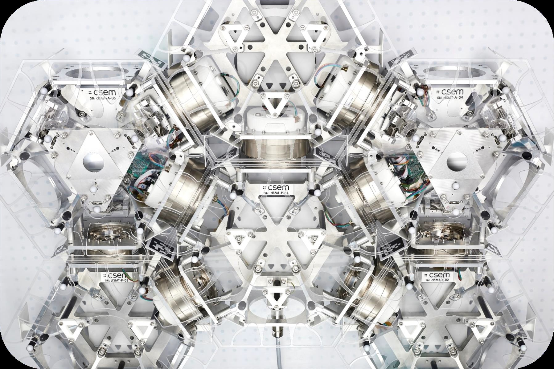
Image Credit: CSEM
Key Specifications & Design Elements
Table 1. Source: CSEM
| Specification |
Value |
| Degrees of freedom |
3: piston, tip and tilt |
| Piston stroke |
± 3 mm |
| Piston resolution |
1 µm |
| Piston repeatability |
< 5 µm |
| Angular stroke |
± 1° |
| Angular resolution |
4 µrad |
| Angular repeatability |
< 20 µrad |
| Tile Shape |
Hexagonal |
| Mass budget |
< 9 kg |
| Dimension |
Width < 400 mm |
Tile Kinematic Architecture
For each leg of the tripod, there is a compliant structure:
- A radially attached linear guide
- A flexure pivot with a single axis
- A flexure gimbal with three-rotation axes
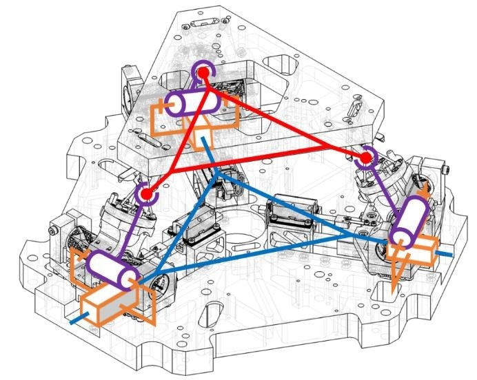
Image Credit: CSEM
Linear Motorized Stage
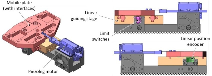
Image Credit: CSEM
Flexible Transmission Stage
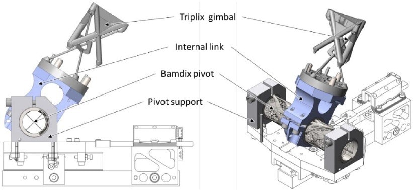
Image Credit: CSEM
Flexible Pivots and Gimbals (Designed and Produced In-house Through SLM Additive Manufacturing)
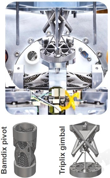
Image Credit: CSEM
Calibration and Performance
Calibration of the Linear Stage
- To relate the motor coordinates to the linear stage displacements, look-up tables were created.
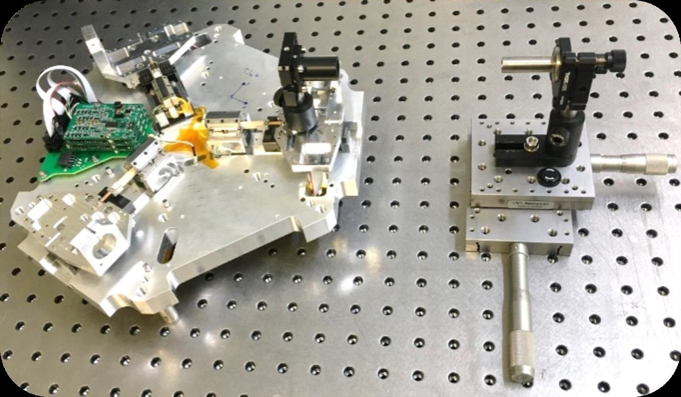
Image Credit: CSEM
- Tile resolutions greater than the desired 4 µrad in tip and tilt and 1 µm in piston due to resolutions better than 350 nm
- The accuracy is in the ± 1.5 µm range
Tile Calibration Setup
- For the measurement of the piston location and tip and tilt angles, an autocollimator and an interferometer containing three heads facing three retroreflectors were used.
Tile Calibration Process
- Using FEM modeling, determine the preliminary geometrical model (IGM)
- Calculation of coordinates for multiple mirror postures using the preliminary IGM
- Modeling of a real-world process IGM utilizing a stepwise regression approach to determine a polynomial model
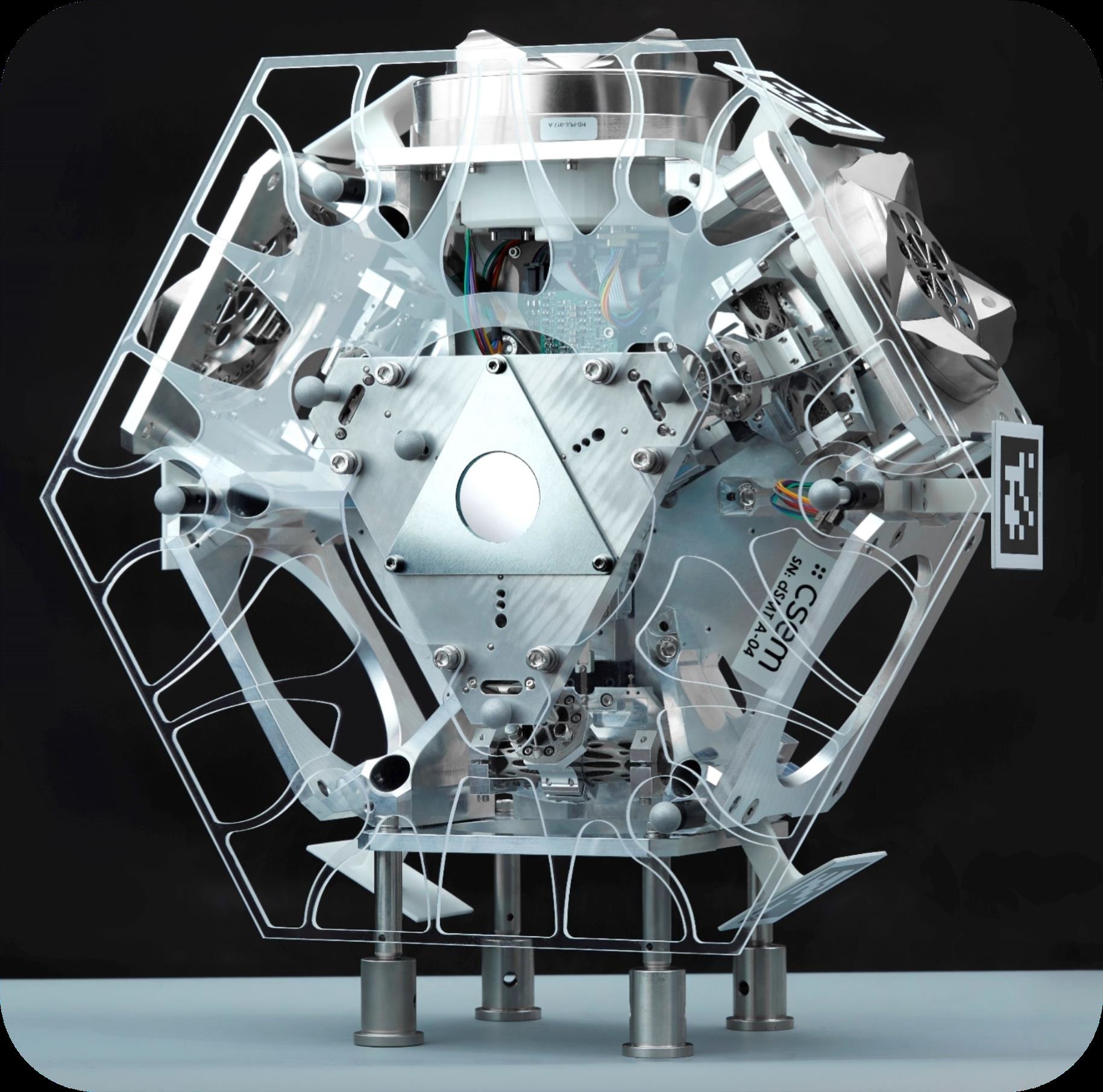
Image Credit: CSEM
Performance Validation
- The tile’s geometric model was calculated using 8000 measured locations
- Two tiles are assembled, calibrated, and identified
- The difference between the desired mirror position and the measured position is calculated for 512 positions over the tile’s whole position space
Table 2. Source: CSEM
| Performance |
Tile1 |
Tile2 |
| Errors |
Tip [µrad] |
Tilt [µrad] |
Piston [µm] |
Tip [µrad] |
Tilt [µrad] |
Piston [µm] |
| Mean |
36.13 |
-46.65 |
-2.12 |
9.96 |
-25.53 |
0.78 |
| Std. deviation |
88.02 |
86.84 |
5.44 |
98.97 |
100.35 |
6.18 |
| Maximum (abs) |
286.87 |
268.96 |
16.25 |
362.19 |
305.79 |
19.06 |
- Over the whole stroke of the mechanism, the two tiles have an overall mirror position precision of about 100 µrad in tip and tilt rotations and about 7 µm in piston translation.
Repeatability Measurements
- The repeatability values are calculated by achieving 64 mirror locations for Tile 1 and 91 mirror positions for Tile 2, ten times each. The sequence in which these places are attained has been randomized to ensure that there will be no bias.
Table 3. Source: CSEM
| Repeatability |
Tile 1 |
Tile 2 |
| Tip |
5.98 ± 1.54 µrad |
8.01± 3.89 µrad |
| Tilt |
3.69 ± 1.25 µrad |
3.67 ± 1.15 µrad |
| Piston |
0.61 ± 0.23 µm |
0.33 ± 0.16 µm |
- The mechanism’s angular repeatability is less than 10 µrad in tip and tilt and less than 1 µm in the piston, which is considerably below the project’s requirements.

This information has been sourced, reviewed and adapted from materials provided by CSEM.
For more information on this source, please visit CSEM.