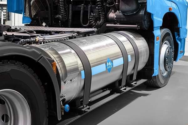
Fuel cell technology is evolving rapidly in the race to reduce carbon emissions. Both lithium-ion battery technology and hydrogen fuel cell systems are contributing to the global effort to reduce carbon dioxide emissions.
Fuel cells are made up of three basic components: two electrodes (anode and cathode) and an electrolyte sandwiched between them. Hydrogen fuel cells used to power electric vehicles are known as Polymer Electrolyte Membrane (PEM) fuel cells because the electrolyte is a proton-conducting polymer membrane.
They are also referred to as proton exchange membrane fuel cells because their electrodes are generally coated with conductive carbon mixed with platinum (Pt) particles. Pt functions as a catalyst in the constant conversion of a fuel (hydrogen) and an oxidant (oxygen) into electricity.
Controlling the Pt coating uniformity and amount or weight on the electrode’s surface during the fabrication process is crucial to achieving effective chemical reactions in the cell while minimizing raw material costs and finished product waste.
This is where one of the relatively simple elemental analytical techniques, energy-dispersive X-Ray fluorescence (EDXRF) spectrometry, can be used for quick quality control to ensure performance, enhance production yield, and support sustainability through waste reduction.

Image Credit: Hitachi High-Tech Analytical Science
Hydrogen Fuel Cells For Cleaner Mobility
Hydrogen fuel cells appear to be the ideal zero-emission energy source. Simply feed the fuel — hydrogen (which is classified as a renewable energy source due to its abundance) — and air to the cell’s electrodes, and the cell generates electricity, heat, and water. The cells emit no greenhouse gases; the only by-products are water and heat, which can be used in some systems to make them even more effective than electricity-producing systems alone.
However, like the lithium-ion battery, which still requires fossil fuels to charge, large amounts of energy from fossil fuels are frequently used to produce hydrogen, making their overall green credentials less positive. Luckily, new hydrogen production processes are being devised, further enhancing the environmental credentials of hydrogen fuel cells.
The situation is improving, however, as renewable energy technologies such as wind and biomass are developed.
Polymer Electrolyte Membrane Fuel Cells (PEMs)
The primary benefit of hydrogen fuel cell technology is that it can be used at relatively low temperatures, and its output can be easily diversified — both of which are required for personal vehicle use.
PEMs use platinum as a catalyst at the anode to transform hydrogen into H+ plus an electron (hydrogen oxidation reaction) and as a catalyst at the cathode to produce oxygen ready for combination with the hydrogen ions to produce water.
The quality of the Pt coating, in terms of weight on film and the presence of iron (Fe) particle contaminants, significantly affects energy cell operation. Particles can enter the iron production process through raw materials and wear and tear on process equipment.
When iron is present in a fuel cell, it can react with hydrogen peroxide (H2O2) to produce free radicals (Fenton reaction). This reaction has the potential to damage the cell's ion-exchange membrane and deteriorate the fuel cell.
Fenton reaction: Fe2+ + H2O2 → Fe3+ + HO. + OH-
H2O2 + HO. → HO2. + H2O
Conventional X-Ray computerized tomography systems require several hours to detect small metal particles in membrane electrode assemblies, and while scanning electron microscopy can detect particles smaller than 10 µm in size, it does not “see” particles within the sample.
Hitachi has created a new particle inspection technology that identifies and analyses metal contaminants as small as 30 µm in as little as 15 minutes, significantly increasing testing throughput. The same technology can also be used to determine the distribution of Pt on the membrane.
EA8000A For the Detection of Metal Contaminants
To locate and characterize metal contaminants within membrane electrode assemblies (MEAs), the EA8000A employs X-Ray transmission technology, optical microscopy, and EDXRF spectrometry. Pt distribution on the membrane is also mapped using EDXRF.
While other techniques frequently identify small particles on the sample’s surface, the EA8000A employs unique, focused X-Ray optics to spot and recognize elements in metal particles deeper within the sample.
Sample preparation is quick and simple: simply place the MEA (maximum size: 250 mm × 200 mm) in the sample jig and place the jig on the analysis stage to perform the evaluation.
The EA8000A measurement stages for a comprehensive analysis are:
- Obtain an optical image of the sample using transmitted X-Rays
- Auto-detect the position of any contaminants using image processing
- Observe morphology and automatically capture an image of contaminated areas
- Carry out elemental mapping of the contaminated areas and/or the whole membrane by EDXRF
- Create a report
These steps can be completely automated, freeing up the operator’s time and increasing productivity.

This information has been sourced, reviewed and adapted from materials provided by Hitachi High-Tech Analytical Science.
For more information on this source, please visit Hitachi High-Tech Analytical Science.