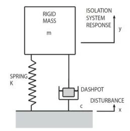
In analysis, it is common practice to conceptualize structures, objects, and isolation systems as basic mass-spring-damper models, as depicted in Figure 42.1.
The mass represented as m is infinitely rigid. The spring is considered weightless, with stiffness determined as K lbs/in. The damper, or dashpot, is weightless, and its damping coefficient is c lbs/in./sec.

Figure 42.1. Typical Isolator Represented as a Mass, Spring and Dashpot. Image Credit: Kinetic Systems, Inc
Natural Frequency
All objects experience vibration when exposed to impact, noise, or vibration. When the source of vibration is eliminated, the object will still experience periodic sinusoidal oscillations, or free vibration at a frequency known as Natural Frequency fn in (Hz cycles/sec).
With minimal or no damping, the Natural Frequency of a simple mass-spring-damper system, as displayed in Figure 42.1, can be characterized using the following equation:
Where mass m = W/g, and
g = acceleration of gravity = 386 in/sec 2
Damping
Damping in a basic system dissipates the energy creating a “dashpot” to reduce the amplification of system response. Actual Damping c is referenced against
Critical Damping c c, which represents the value of damping at which a system will not oscillate when displaced from its equilibrium.
Critical Damping corresponds to system mass and natural frequency, as follows:
Forced Vibration, Transmissibility and Resonance
If subjecting the simple isolation system (Figure 42.1) to Forced Vibration at frequency f, and sinusoidal foundation motion as shown as amplitude x, the absolute value of the mass response amplitude y defined as a ratio |y/x|, also referred to as Transmissibility T, will be expressed as follows:
 |
(3) |

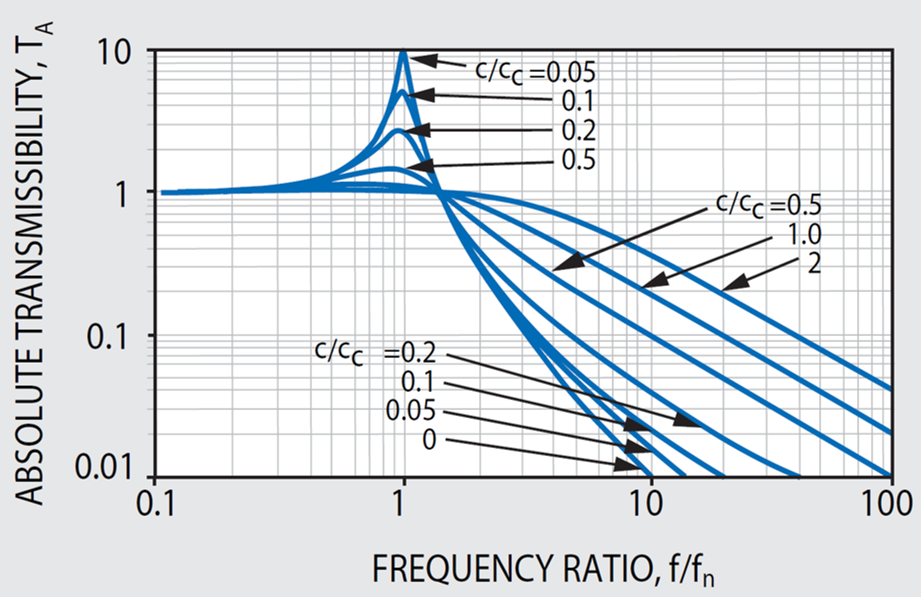
Figure 42.2. Influence of Damping in Vibration Isolation. Image Credit: Kinetic Systems, Inc
Figure 42.2 has been charted as a function of forcing frequency ratio f/f n and critical damping ratio c/c c. If executing external vibrations at a frequency that correlates with the Natural Frequency, i.e., (f/f n )= 1, a condition of Resonance emerges. At resonance, the system be subjected to a significantly large and conceivably damaging amplification of the disturbing forces.
The maximum Transmissibility T max at resonance is frequently characterized as the Q of the system and is more or less associated with Critical Damping, as follows:
Dashpot or damping force corresponds with the velocity. The forces that result from high damping are required at resonance to counteract magnification that may cause damage, but these forces are less desirable at high frequencies due to the fact they may negate vibration attenuation. This is shown in Equation (3).
Isolation Efficiency
Isolation Efficiency E in percent transmission corresponds to Transmissibility as:
This also represents the percentage of the vibration isolated from the payload. To ensure the best isolation efficiency is achieved, the isolator’s natural frequency should be very low as observed in Equation (3) and Figure 42.2. This is the fundamental philosophy that underpins VIBRAPLANE Isolation.
Center of Gravity (cg)
The center of gravity is the location in an object where an applied external force produces displacement without any rotation. Usually, the center of gravity will be pinpointed close to the largest concentration of mass in the object and may be determined via computation or experimental means.
Equipment cg height and geometry are crucial for making considerations of stability and sway when soft supports are being used to achieve vibration isolation. For optimal results, KSI advises that the cg height should not surpass 25 % of the shortest span between supports.
Air Spring Stiffness and Natural Frequency
VIBRAPLANE isolation systems leverage the properties of compressed air to deliver remarkably low stiffness, a property key for achieving high-efficiency broad frequency band isolation for high technology equipment.
The Air Spring Stiffness K in lbs/in. is a function of absolute pressure P in psi, area A in sq. in., and volume V in cu. in., as shown below:
When Equations (1) and (6) are combined, the simple Air System Natural Frequency is:
| f A = 3.13 (A / V) 1/2 |
(7) |
It should be noted that in Equation (7) an increase of the air volume of the air spring results in a reduced system natural frequency which is required for high isolation efficiency.

This information has been sourced, reviewed and adapted from materials provided by Kinetic Systems, Inc.
For more information on this source, please visit Kinetic Systems, Inc.