The AirSentry® II AMC Multipoint Monitoring System can be set up in such a way that point-specific concentration tags (sample location concentration data) are easy to access and managed by FacilityNet, not only in the onboard Supervisory Control and Data Access (SCADA) software, iFix™.
Once the appropriate configuration has been selected in FacilityNet, all the system’s features, including automated notifications, status indicators, and graphical tools can be utilized to their fullest extent.
Once the relevant tags have been configured, it is also possible to make the data accessible to any other OPC protocol-driven software within the manufacturing TCP/IP network via the onboard FacilityNet OPC Server.
It should be noted that point-specific concentration tags are available in the SCADA (iFix) software server for the AirSentry® II Multipoint Monitoring System via OPC. However, users may choose to use the FacilityNet OPC server to connect to a single OPC server for tags that are made available in addition to the concentration tags.
The additional tags include the AirSentry II Analyzer ‘state’ tags such as Ambient Pressure, CDA Pressure, Cell Temperature, Dopant Temperature, and Vacuum Pressure.
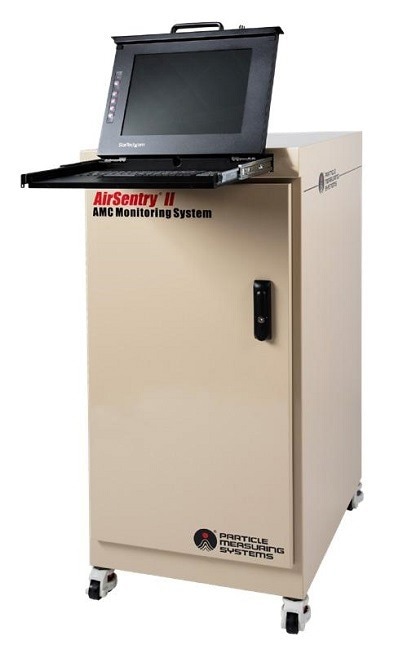
Figure 1. Airsentry II AMC Multipoint Monitoring System. Image Credit: Particle Measuring Systems
This paper will describe how to introduce these point-specific concentration data tags into the local FacilityNet OPC Driver application for use on the integrated industrial computer. This process transmits the data to the FacilityNet OPC server, which can be accessed from other OPC data handling systems.
The paper highlights the step-by-step procedure for generating automated notifications that are created whenever user-defined limits are applied to any data tags in FacilityNet (for use of additional FacilityNet features, please see the FacilityNet Operations Manual)
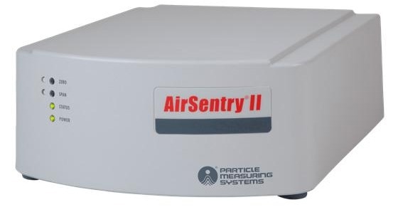
Figure 2. Airsentry II POU Analyzer Unit. Image Credit: Particle Measuring Systems
AirSentry® II AMC Multipoint Monitoring System Introduction
The AirSentry® II AMC Multipoint Monitoring System (AMC Monitoring System) was developed to monitor airborne molecular contamination (AMC) across 16 or 30 sample points that are distributed within high-end manufacturing environments and cleanroom facilities. The system incorporates a 16- or 30-point valve actuator that rotates at sample intervals determined by the user between individual sample locations; the onboard SCADA software controls the movement of this valve actuator, a system often referred to as a manifold.
During the sample interval for each sample point, undisturbed sample gas passes through sample tubing from the remote sample point location to the AirSentry II (ASII) units placed in the centralized manifold system cabinet.
The AirSentry II AMC Monitoring System allows for the installation of up to 3 ASII analyzers to detect AMC concentrations for Total Amines, Total Acids, Ammonia, or Chlorides with precision down to 200, 200, 200, and 500 pptv, respectively.
For detailed information on the AMC Monitoring System and AirSentry II units, the manuals of each serve as the best point of reference. iFix is the central control system of the AirSentry II AMC Monitoring System, iFix also functions as a data access software package and offers the necessary user GUI to facilitate multipoint sampling customization. A general software scheme is outlined in Figure 3.
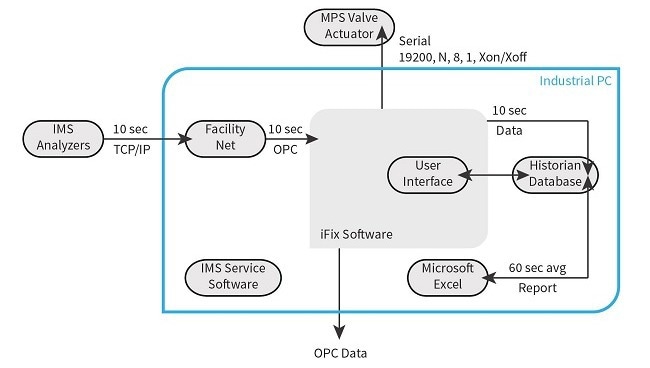
Figure 3. IFIX General Software Scheme. Image Credit: Particle Measuring Systems
The physical layer is comprised of all the Ethernet and serial cable connectivity points that link the industrial computer to the AirSentry II Analyzers (up to 3) and the Multi-Point System (MPS) manifold valve in the AMC Monitoring System. The Industrial PC runs the SCADA software that incorporates analyzer data tags with the sample valve positions in real-time. The PMS Software program FacilityNet collects the data from the ASII analyzer data.
At the same time, the iFix software controls the MPS valve position in line with the user-defined sample sequence settings. The iFix software also gathers the FacilityNet data via OPC once every 10 seconds. The ASII real-time continuous data is then synchronized and displayed via iFix with the MPS valve position marked for each location.
This point-specific data can be accessed via the iFix OPC Server which is stored in the database software called Historian. From the iFix OPC Server, the real-time, non-continuous, point-specific data can be viewed via OPC with the use of external OPC-compatible software packages that are linked via TCP/IP.
FacilityNet can be used as an OPC Client to collect this point-specific data into its OPC driver.
The user interface of iFix makes it possible to switch between automatic or manual control of sample settings, data downloading for report viewing or exporting, and real-time graphing of sample point trends, alarm displays, and notifications. The interface is displayed in Figure 4.
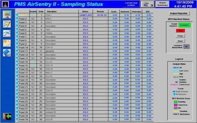
Figure 4. The IFIX Interface Data Sampling Status Screen. Image Credit: Particle Measuring Systems
Adding Point-Specific Concentration Data to Facility Net via OPC
Before initiating the process, ensure the following protocols are in place:
- This is being performed on the AirSentry® II AMC Multipoint Monitoring System.
- The CPU is switched on and logged in to the user with relevant administrative privileges.
The following instructions guide users through introducing point-specific concentration data to FacilityNet via OPC:
1. On the Desktop, open the “AMC Monitoring System” application. This will launch iFix, Historian, and FacilityNet.
2. Log-in to iFix and FacilityNet, and make sure the ASII analyzers are connected and functioned as they should in FacilityNet and iFix (default settings are username: admin and password: s@nit@s for both).
3. In FacilityNet, select Configure Instruments button

Image Credit: Particle Measuring Systems
4. Highlight the Network folder and click “Add.”
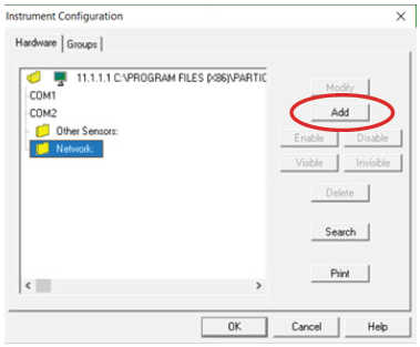
Image Credit: Particle Measuring Systems
5. Click on the third tab: “Add Other.” Then click “OPC client” and select “Okay”. This will launch the OPC Client Configuration window.
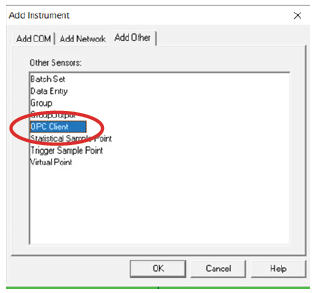
Image Credit: Particle Measuring Systems
6. A new window will pop up. In “OPC Name”, give this set of data a title (Example: AirSentry II AMC Multipoint monitoring System in Litho Area). Note: This procedure will use “iFix OPC Example”. Then click “Select…” to choose the OPC server.
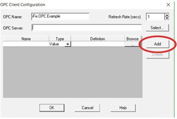
Image Credit: Particle Measuring Systems
7. In the new window, click “Intellution.OPCiFix.1” and followed by “OK”. This is the OPC server created by iFix.
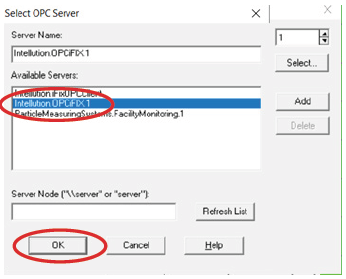
Image Credit: Particle Measuring Systems
8. Now in the OPC Client Configuration window, the grey button with “…” under the “Browse” section should be selected to add the desired data tag. It may take up to five minutes for the next window to load.
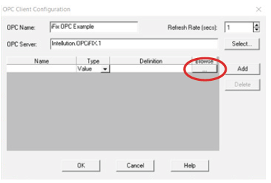
Image Credit: Particle Measuring Systems
9. Scroll down until you can see a line that reads the exact text: “PMS.ASII_01A_CONC.F_CV”. Select this tag and press OK. You can bypass this step and type “PMS.ASII_01A_CONC.F_CV” directly into the Definitions box. Then, write the name of the location in the highlighted section. For the primary analyzer at the first location of the AMC Monitoring System. In this case, “Port 01A” is used.
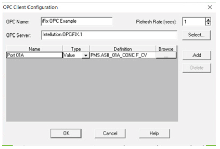
Image Credit: Particle Measuring Systems
Note: The concentration tags should display the following naming convention: “Fix32.PMS.ASII_{point name}{analyzer label}_CONC.F_CV”, where {point name} = “01”, “02”, “03”..”16” or ...“30”
{analyzer label} = factory settings which will always assign “A” to be linked to data from the ASII analyzer, ordered alphabetically; “B” would be from the second analyzer also in alphabetical order, and “C” would be used if three analyzers were being used.
All concentration tags will display the suffix “_CONC.F_CV” e.g. If the system contains Amines, Chlorides, and Acids ASII units, then the tags would be arranged as follows: “A” will be linked to Acids; “B” to Amines; and “C” to Chlorides. It should be noted that in the case only Acids and Amines are installed, “A” would be linked to Acids and “B” would be linked to Amines.
10. Copy the text in the Definition tab, and then select “add”.
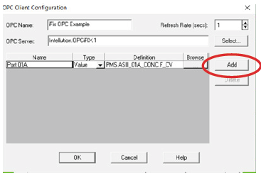
Image Credit: Particle Measuring Systems
11. Another line in the table will pop up. Paste the text copied over from the previous step into the blank “Definition” column but where “01” appears, delete and re-enter as “02”. It should now read “PMS.ASII_02A_CONC.F_CV”. This now shows the data from the primary analyzer at the second location of the AMC Monitoring System. Finally, name the line: In this example, the “Port 02A” is used.
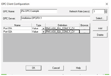
Image Credit: Particle Measuring Systems
12. Repeat steps 9 and 10 for all relevant locations of the AMC Monitoring System, ensuring the number to the port number of the manifold is changed. If there are several ASII analyzers present in the AMC Monitoring System, steps 9 and 10 should be repeated, except replace the “A” with a B, and C for all relevant points in the manifold.
For instance: “PMS.ASII_01B_CONC.F_CV” for location 1 of the second analyzer and “PMS.ASII_01A_CONC.F_CV”, and “PMS.ASII_01C_CONC.F_CV” for the 3rd analyzer.
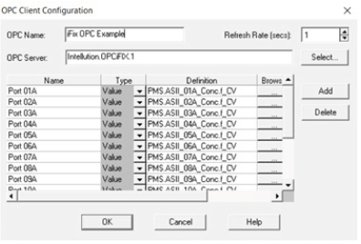
Image Credit: Particle Measuring Systems
13. When all analyzer and locations have been entered, select “OK” in the OPC Client Configuration
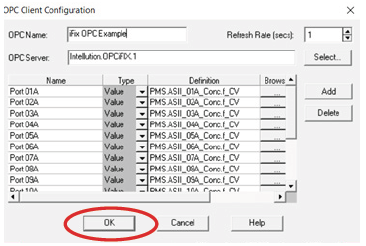
Image Credit: Particle Measuring Systems
14. Click “OK” once again in the Instrument Configuration.
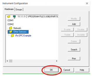
Image Credit: Particle Measuring Systems
That concludes the process of adding data at each location of the AMC Monitoring System and entering it into FacilityNet.
All the AMC Monitoring System sample locations that have been entered will then populate in FacilityNet. Green verifies that they are connected to the iFix OPC Server and that the data is being transmitted. It will populate the data on a 10-second sample delay.
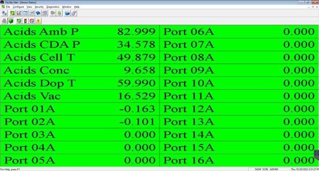
Figure 5. FacilityNet Sampling Screen for the AMC Monitoring System Connected to the iFix OPC Server. Image Credit: Particle Measuring Systems
Now that this is complete, all the functionality of FacilityNet can be used: alarms, email alerts, graphing functions, etc. When the instrument is not sampling a specific location, the last known data will appear in that location.
Enabling Alarms in Facility Net
Once FacilityNet has received all of the relevant input related to the point-specific concentration data of the AMC Monitoring System, then all the functionality of FacilityNet’s system can be accessed. One of the key features that can now be activated is alarms; in this section, the process of setting alarms will be outlined. For additional information on alarms or other FacilityNet features, review the FacilityNet Operations Manual.
1. Selecting the Alarm Limits button on the Sensor Status window toolbar  opens the Alarm Settings window will open.
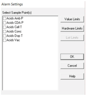
Image Credit: Particle Measuring Systems
2. Click Sample Point(s) list box to reveal the sample point(s) you want to configure. To select several items, hold down the Ctrl key. Then click Value Limits.
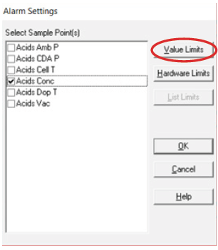
Image Credit: Particle Measuring Systems
3. Facility Net has four levels of alarms numbered 0, 1, 2, and 3, each of which increases in severity. Activate each alarm level, check the check box, and then set the desired control levels. In this case, it is the “PPB” check box.
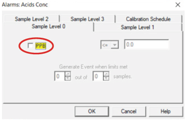
Image Credit: Particle Measuring Systems
4. Use the drop-down menu to choose the preferred limit and enter the specific limit, then edit the “Generate Event when limits met” to the desired amount. Then click “OK”.
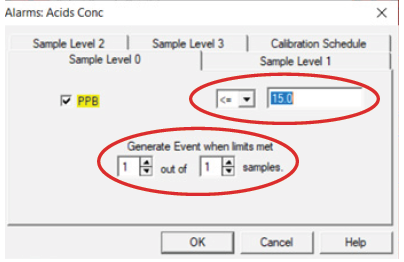
Image Credit: Particle Measuring Systems
5. Repeat this process for all alarm levels. Then click “OK”.
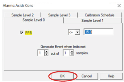
Image Credit: Particle Measuring Systems
Enabling Automated Notifications for Limit Violations
FacilityNet can send email notifications in the event of an alarm or another key alert. This can be set up by defining a user/email server for the notifications to be sent. To ensure this is initiated, a job needs to be created. For this process to be completed, follow the instructions in the FacilityNet Operations Manual.
Facility Net OPC Server
FacilityNet also functions as an OPC service to transmit data to an OPC client to connect this data with another system (Note: The FacilityNet OPC driver is an add-on that must be purchased in addition to FacilityNet software and does not come included in a standard purchase).
When FacilityNet is launched it “registers” itself so that clients can find it. This registration involves setting a set of specific registry entries.
The FacilityNet Server identifiers (to send data to OPC client) are:
ProgID = ParticleMeasuringSystems.FacilityMonitoring.
CLSID = { 0xe2d8e9c0, 0xede0, 0x11d3, { 0xb2, 0xab, 0x0, 0xe0, 0xb8, 0x11, 0xc6, 0xa7 } };
After FacilityNet has been shut down it remains registered. However, users can only connect to the FacilityNet OPC server when in service. For more information regarding setting up and communicating with the FacilityNet OPC Server, please see the FacilityNet™ OPC Driver Tutorial document. The FacilityNet™ OPC Driver Tutorial document is now available from Software Support ([email protected]).
Conclusion
The AirSentry® II AMC Multipoint Monitoring System leverages the functions of FacilityNet and iFix to operate the main system. From the factory, the manifold system does not include the point-specific concentration in Facility Net, only iFix. Herein, we detailed an overview of how to add the information and data created by the iFix program into Facility Net via the OPC server.

This information has been sourced, reviewed and adapted from materials provided by Particle Measuring Systems.
For more information on this source, please visit Particle Measuring Systems.