Carbon fiber reinforced plastic (CFRP) is recognized for its excellent specific stiffness and specific strength. It is used in a range of sectors, such as the transportation industry.
To use CFRP as a structural material, assessing fatigue is vital for durability and reliability because it is a leading cause of structural failure.
While traditional fatigue testing machines take several months for a 109 cycle fatigue test, the Shimadzu USF-2000A ultrasonic fatigue testing system provides fatigue testing at a 20 kHz frequency, enabling the completion of a 109 cycle fatigue test in around 14 hours.
Using the USF-2000A is a practical technique to evaluate long-term durability and reliability. This article outlines a case study of a three-point bending ultrasonic fatigue test of CFRP utilizing the USF-2000A.
System Advantages
- The Shimadzu USF-2000A ultrasonic fatigue testing system provides fatigue testing at 20 kHz, allowing a fatigue test of 109 cycles to be completed in approximately 14 hours
- A straightforward three-point bending test of carbon fiber reinforced plastic (CFRP) can be performed with the ultrasonic fatigue testing system
- A high-speed video camera can be used to view the behavior of specimens vibrating at 20 kHz
Measurement System
Figure 1 presents the experimental system setup. The investigation was performed using a three-point bending indenter and a prototype of a three-point bending jig for ultrasonic fatigue testing, derived from the USF-2000A’s average stress loading mechanism.
The sample prepared for testing was a CFRP specimen measuring 40 mm in length, 7 mm in width, and 3.5 mm in thickness. As ultrasonic fatigue testing requires resonance of the specimen at 20 kHz, a span that will resonate at 20 kHz is vital.
In this study, the span was set to 16.5 mm. The instrument settings are outlined in Table 1.
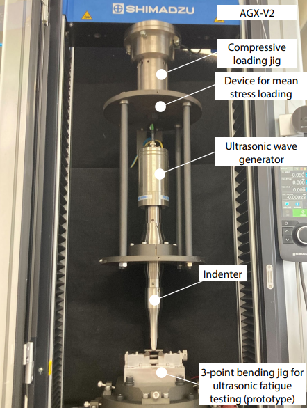
Figure 1. Test conditions. Image Credit: Shimadzu Scientific Instruments
Table 1. Configuration of the instrument. Source: Shimadzu Scientific Instruments
| . |
. |
| Ultrasonic fatigue testing system |
USF-2000A |
| Precision universal testing machine |
AGX-V2 |
| Test jigs |
Device for mean stress loading
Compressive loading jig
Indenter (R5)
3-point bending jig for ultrasonic fatigue testing (support R2) |
| Software |
Super Sonic |
| High-speed video camera |
HPV-X2 |
| Radiation thermometer |
FT-H10 (KEYENCE) |
Recording of the Specimen Under Test
An HPV-X2 high-speed video camera was used to observe the specimen’s behavior during the test before starting the main ultrasonic fatigue test.
Figure 2 displays the arrangement of the high-speed recording. A random pattern for Digital Image Correlation (DIC) analysis was applied to the specimen, and the high-speed recording frame rate was set to 1 Mfps. Figure 3 portrays an example frame taken during the high-speed recording.
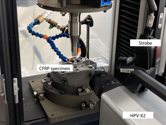
Figure 2. Condition of high-speed recording. Image Credit: Shimadzu Scientific Instruments
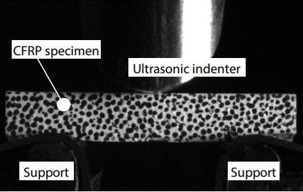
Figure 3. Example of image captured by high-speed recording. Image Credit: Shimadzu Scientific Instruments
Figure 4 shows a sample DIC analysis outcome. The graph in Figure 4 demonstrates the displacement in the test axial direction at a location directly below the ultrasonic indenter. The sine wave directly below the indenter confirmed satisfactory loading.
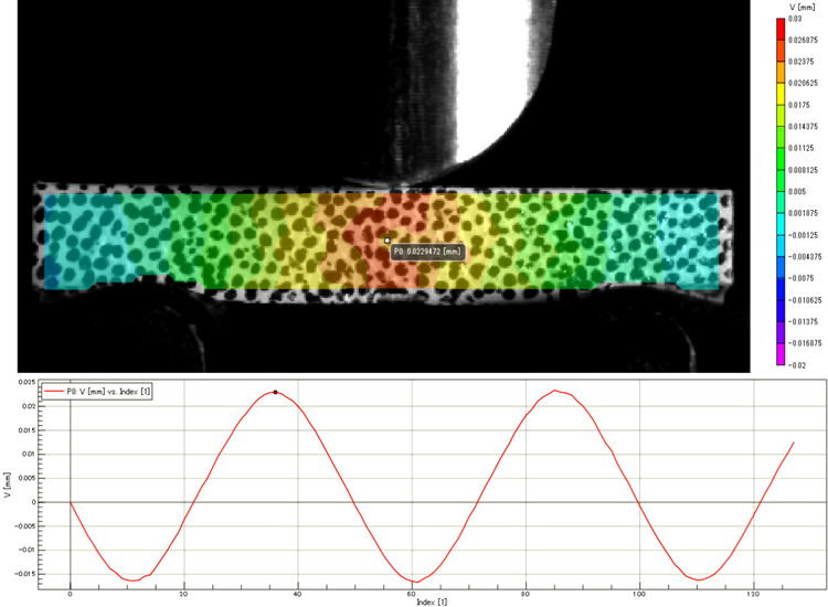
Figure 4. Example of results of DIC analysis. Image Credit: Shimadzu Scientific Instruments
Static Three-Point Bending Test Results
The static three-point bending test results are presented in Figure 5. In this analysis, the maximum test force was 3479 N.
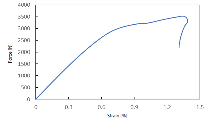
Figure 5. Force-strain diagram. Image Credit: Shimadzu Scientific Instruments
Results of Three-Point Bending Ultrasonic Fatigue Test
Figure 6 shows the arrangement of the three-point bending ultrasonic fatigue test. To prevent heat build-up in the test samples, cooling via an air cooler, along with interval operation where oscillation was turned on and off in cycles, was employed.
A radiation thermometer was used to measure the surface temperature of the samples. The test conditions are displayed in Table 2. The applied test force in the ultrasonic fatigue test was equal to between 65 and 85% of the peak test force in the static 3-point bending test.
Tests were additionally performed using a traditional fatigue testing machine under a greater test force, leading to a lower cycle count before fracture.
Figure 7 presents this data alongside the results of the three-point bending fatigue test utilizing the USF-2000A. The results from the traditional fatigue tester and the USF-2000A were broadly consistent, demonstrating the USF-2000A's accuracy.
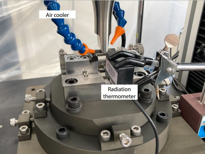
Figure 6. Three-point bending ultrasonic fatigue test. Image Credit: Shimadzu Scientific Instruments
Table 2. Conditions of fatigue test. Source: Shimadzu Scientific Instruments
| . |
. |
| Loading condition |
65% - 85% of static bending strength |
| Stress ratio |
0.7 |
| Frequency |
20 kHz |
| Maximum number of cycles |
1 × 10⁹ |
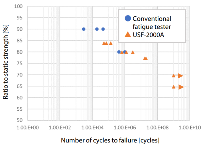
Figure 7. Stress versus number of cycles (S-N) Diagram. Image Credit: Shimadzu Scientific Instruments
Conclusion
The USF-2000A ultrasonic fatigue testing system was used to perform a three-point bending ultrasonic fatigue test. The test results were broadly consistent with the results of a traditional fatigue test, indicating the potential of the USF-2000A to be deployed in three-point bending fatigue tests of CFRP. The time needed for fatigue testing can be significantly reduced by adopting this system.
Acknowledgments
Produced from materials originally authored by Fumiaki Yano and Tsubasa Yamamoto from Shimadzu Corporation.

This information has been sourced, reviewed, and adapted from materials provided by Shimadzu Scientific Instruments.
For more information on this source, please visit Shimadzu Scientific Instruments.