A visual examination by Element Materials Technology of the sensor revealed significant cracking within the head portion of the sensor jacket. Microscopic inspection of the part revealed that the overall fracture surface exhibited a relatively coarse texture, indicative of ductile rupture.
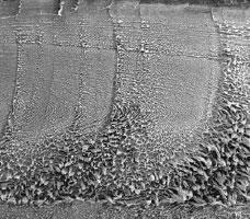
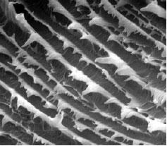
A distinct crack origin was apparent along the outer wall of the jacket. The sample was further examined via SEM. The morphology of the fracture surface at the origin was relatively flat, indicating brittle cracking. Surrounding the crack origin, unique features, characteristic of crack propagation and arrest through a cyclic mechanism were apparent. Additionally, significant ductility was indicated by the presence of stretched fibrils on the fracture surface.

Figure 1. The sensor jacket fracture surface shows signs of alternating crack and arrest sequences (SEM Original Mag. 20X).

Figure 2. True fatigue-like striations were apparent on the fracture surface (SEM Original Mag. 1000X).
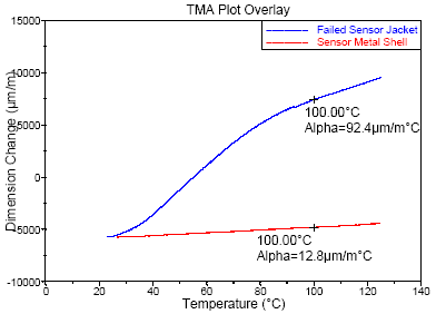
Analytical testing, including FTIR and DSC, produced results consistent with an unfilled PFA resin. The melt flow rates of the failed sensor jacket material and a submitted control sample of the molding resin produced comparable results, indicating that the material did not undergo molecular degradation during the molding operation. Thermomechanical analysis (TMA) was used to evaluate the jacket material and the underlying steel shell. The results were consistent with those expected for PFA resin. However, the data illustrated a significant difference in the coefficients of thermal expansion between the two materials over the anticipated temperature range the part would experience in service.

Figure 3. The TMA results showed significant differences in the coefficients of thermal expansion of the sensor plastic jacket and steel shell materials.
Conclusion
It was the conclusion of the Element Materials Technology investigation that the sensor initially cracked via brittle fracture. The fracture surface morphology was consistent with the exertion of low level stresses, below the yield point of the material, over a prolonged period of time. A significant source of the stress appeared to be the interference between the PFA jacket and the underlying steel shell. These stresses would be particularly exaggerated under conditions of subambient temperature exposure. Under these conditions the polymeric jacket would contract significantly around the steel shell, as supported by the TMA results. Given the location of the fracture origin, it is likely that this area represents a potential knit line on the part, resulting from inadequate fusion of the plastic flow fronts during molding. Once the cracking initiated, the fracture appears to have propagated via a cyclic mechanism. This is likely the result of the alternating heating and cooling cycles associated with normal service and the cleaning operation. No evidence was found to indicate deficiencies in the PFA molding material, or degradation to the material, either as a result of the molding process or service conditions.
Fatigue and Fracture In Environment - Extended Version
Video Credit: Element Materials Technology

This information has been sourced, reviewed and adapted from materials provided by Element Materials Technology.
For more information on this source, please visit Element Materials Technology.