|
It must be made clear that polymers respond to applied loads very differently to metals, making direct comparisons of strength and stiffness of limited use. For example, a large number of design formulae have been derived for beams, plates and columns dependent on the elastic modulus as a fundamental measure of the response of the material to stress, the implicit assumption being that the material behaves in a linear, elastic manner until yielding.
For most metals, this is true; for polymers, the stress-strain curve is rarely linear, there is no true proportional limit and the behaviour is greatly affected by strain rate and temperature. Because a polymer behaves in a manner that seems to combine elastic solid and highly viscous behaviour, they are termed 'viscoelastic'.
Deformation
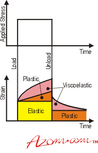
The deformation of polymer components subjected to external stress is composed of three elements (see figure1):
- Instantaneous (reversible) elastic deformation;
- Time-dependent viscoelastic deformation;
- Time-dependent irreversible plastic deformation.
|

|
|
Figure 1. Breakdown of the strain response of a typical polymer as a function of stress and time.
|
This time-dependent behaviour means that test methods must be carefully defined and data sheet values must be used with care. (ISO 10350 and ISO 11403 are current international standards for single and multi-point data respectively.)
Viscoelastic Creep
Viscoelastic materials creep under steady stress and relax under steady strain. In order to design a component that will not creep more than, say, 1% over its projected lifetime, it will be necessary to examine creep curves from the material supplier to ascertain the stress level that will restrict creep to this limit.
Tensile Strength
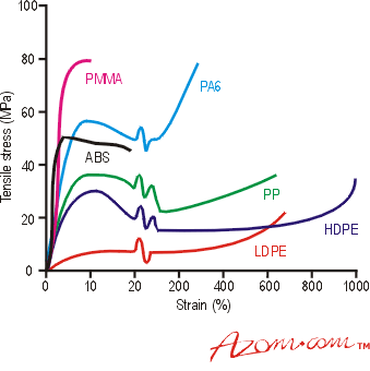
Tensile test results may be useful in the preliminary selection of materials, but are only really of any further use to the designer if the strain rate experienced by the component in service is similar to that used in the test. Typical stress-strain curves for a number of polymers are shown in figure 2.
|

|
|
Figure 2. Typical stress-strain curves for various types of polymers (PMMA – Polymethylmethacrylate, PA6 – Polyamide/Nylon, ABS – Acrylonitrile Butadiene Styrene, PP – Polypropylene, HDPE – High Density Polyethylene, LDPE – Low Density Polyethylene).
|
Anisotropy
The designer of a polymer component always needs to be aware of the anisotropic nature of these materials, particularly those reinforced with fibres. As a consequence of the manufacturing process, alignment of polymer chains and any fillers or fibres tend to occur in the direction of flow. While mechanical properties in that direction may be very good, the properties at right angles to the flow direction may be very poor and will almost certainly be different. Of course, this can be viewed as an advantage such that by appropriate mould design, the alignment occurs in regions of high stress where it is needed.
Impact Strength
The Izod and Charpy impact values provide a useful indication of the material's toughness. Comparative figures for notched and unnotched specimens also enable notched impact resistance to be assessed. Actual component behaviour cannot be determined from such data because of variations in loading pattern and part geometry. Also, materials may withstand a blow of impact energy below that deemed necessary to result in fracture, but a second blow at that energy level may be enough to cause fracture. Amorphous polymers such as Polycarbonate (PC) are susceptible to this behaviour, whereas semi-crystalline materials such as Polyamides (PAs) and Polyoxymethylene (POMs) usually perform well under repeated impact loadings. The impact strength of polymers is highly temperature dependent.
|