An RTD (resistance temperature detector) is a temperature sensor that operates on the measurement principle that a material’s electrical resistance changes with temperature.
The relationship between an RTD’s resistance and the surrounding temperature is highly predictable, allowing for accurate and consistent temperature measurement. By supplying an RTD with a constant current and measuring the resulting voltage drop across the resistor, the RTD’s resistance can be calculated, and the temperature can be determined.
RTD Materials
Different materials used in the construction of RTDs offer a different relationship between resistance and temperature. Temperature sensitive materials used in the construction of RTDs include platinum, nickel, and copper; platinum being the most commonly used. Important characteristics of an RTD include the temperature coefficient of resistance (TCR), the nominal resistance at 0 degrees Celsius, and the tolerance classes.
The TCR determines the relationship between the resistance and the temperature. There are no limits to the TCR that is achievable, but the most common industry standard is the platinum 3850 ppm/K. This means that the resistance of the sensor will increase 0.385 ohms per one degree Celsius increase in temperature. The nominal resistance of the sensor is the resistance that the sensor will have at 0 degrees Celsius.
Temperature Sensors - Directly Welded Wires - Innovative Sensor Technology IST AG
Although almost any value can be achieved for nominal resistance, the most common is the platinum 100 ohm (pt100). Finally, the tolerance class determines the accuracy of the sensor, usually specified at the nominal point of 0 degrees Celsius. There are different industry standards that have been set for accuracy including the ASTM and the European DIN. Using the values of TCR, nominal resistance, and tolerance, the functional characteristics of the sensor are defined.
RTD Configurations
In addition to different materials, RTDs are also offered in two major configurations: wire wound and thin film. Wire wound configurations feature either an inner coil RTD or an outer wound RTD. An inner coil construction consists of a resistive coil running through a hole in a ceramic insulator, whereas the outer wound construction involves the winding of the resistive material around a ceramic or glass cylinder, which is then insulated.
The thin film RTD construction features a thin layer of resistive material deposited onto a ceramic substrate through a process called deposition. A resistive meander is then etched onto the sensor, and laser trimming is used to achieve the appropriate nominal values of the sensor. The resistive material is then protected with a thin layer of glass, and lead wires are welded to pads on the sensor and covered with a glass dollop.
Thin film RTDs have advantages over the wire wound configurations. The main advantages include that they are less expensive, are more rugged and vibration resistant, and have smaller dimensions that lead to better response times and packaging capabilities. For a long time wire wound sensors featured much better accuracy. Thanks to recent developments, however, there is now thin film technology capable of achieving the same level of accuracy.
Operations of RTD
An RTD takes a measurement when a small DC current is supplied to the sensor. The current experiences the impedance of the resistor, and a voltage drop is experienced over the resistor. Depending on the nominal resistance of the RTD, different supply currents can be used. To reduce self-heating on the sensor the supply current should be kept low. In general, around 1mA or less of current is used.
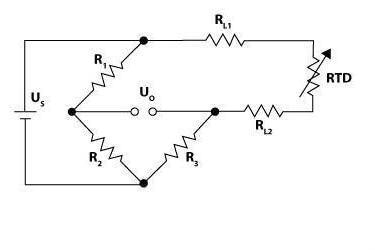
An RTD can be connected in a two, three, or four-wire configuration. The two-wire configuration is the simplest and also the most error prone. In this setup, the RTD is connected by two wires to a Wheatstone bridge circuit and the output voltage is measured. The disadvantage of this circuit is that the two connecting lead wire resistances add directly two the RTD’s resistance and an error is incurred.
2-Wire Configuration

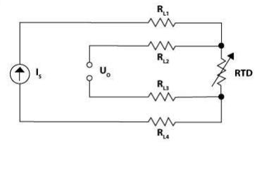
The four-wire configuration consists of two current leads and two potential leads that measure the voltage drop across the RTD. The two potential leads are high resistance to negate the effect of the voltage drop due to current flowing during the measurement.
This configuration is ideal for canceling the lead wire resistances in the circuit as well as eliminating the effects of different lead resistances, which was a possible problem with the three-wire configuration. The four-wire configuration is commonly used when a highly accurate measurement is required for the application.
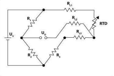
3-Wire Configuration

The four-wire configuration consists of two current leads and two potential leads that measure the voltage drop across the RTD. The two potential leads are high resistance to negate the effect of the voltage drop due to current flowing during the measurement.
This configuration is ideal for canceling the lead wire resistances in the circuit as well as eliminating the effects of different lead resistances, which was a possible problem with the three-wire configuration. The four-wire configuration is commonly used when a highly accurate measurement is required for the application.
4-Wire Configuration

In combination with the wiring diagrams shown, a more complex circuit is often employed. There are many different options for circuits when working with an RTD. The two most important features of this circuit are current generation and signal conditioning.
For purposes of linearity, it is important that the current generation circuit supplies a stable excitation to the RTD. Once a stable excitation current is applied to the RTD, the signal conditioning path of the circuit cancels lead resistances, gains the signal and converts the signal to digital using an ADC, which can then be read by a controller.
Benefits of Thin Film RTD
There are many options when considering contact temperature measurement, including thermocouples, thermistors, and RTDs (wire wound and thin film). While thermocouples can handle very high temperatures and thermistors are inexpensive, there are many advantages of RTDs.
Some of these advantages include their accuracy, precision, long-term stability, and good hysteresis characteristics. Even beyond these, there are advantages of thin film RTDs over wire wound, including smaller dimensions, better response times, vibration resistance, and relative inexpensiveness. New advancements has even made thin film technology just as accurate as wire wound at higher temperatures ranges.

This information has been sourced, reviewed and adapted from materials provided by Innovative Sensor Technology, USA Division.
For more information on this source, please visit Innovative Sensor Technology, USA Division.