Sponsored by XradiaApr 22 2013
In order to characterize the reliability of a packaging process and to identify existing or potential failures in the package, especially in a package having complex wire bonding, the dimensions and proximity of the wire connections before and after encapsulation need to be determined. Traditional methods to make this measurement are tedious and destructive making it practical to measure a single wire on a specific part.
The VersaXRM
The high-resolution and 3D capabilities of the VersaXRM family offer a complete non-destructive method to determine essential parameters of wire bonds. An example of the 3D data potential is shown in Figure 1 is of a part imaged by the MicroXCT. It is possible to cross section this computer-based data set into two-dimensional slices of any desired orientation. Three-dimensional X-ray microscopy thus offers a flexible way to characterize shapes, dimensions and proximity of many of the wire bonds and features in a complex package.
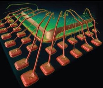
Figure 1. 3D rendering of a wire bonded package. The 3D volume was created through a tomography generated by the MicroXCT-200.
In comparison with the three-dimensional tomography information offered by the VersaXRM family, non-destructive 2D X-ray radiography can miss critical information. Figure 2 shows X-ray image of a similar package that has failed due to an electrical short. Take note that the wire has two different diameters; the thinner carries a signal and the thicker carries power.
By examining the failed component with 2D X-ray imaging as shown in Figure 2 is inconclusive because it did not provide sufficient depth information to reveal whether or not the wires were shorted together, or whether the large diameter wire was simply passing over the thinner wire.
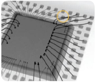
Figure 2. A 2D X-ray image of a wire-bonded package
The 3D microscope image taken by the Xradia MicroXCT as shown in Figure 3 upper section shows that the two wires were actually in contact with one another. In Figure 3 lower section, a virtual cross-section of the 3D data confirms that the wires are close enough to be the cause of the electrical short.
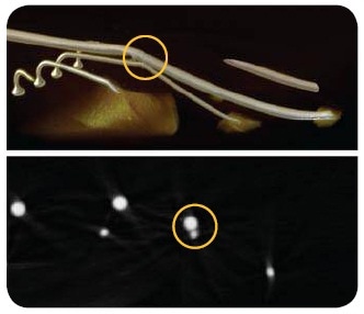
Figure 3. Upper-3D rendering of two wires suspected of touching.
Lower figure: Virtual cross section of 3D image at the location of the yellow line confirms the wires are touching.
Wire Bond Measurement Examples
The traditional technique used to make this measurement after encapsulation requires a physical cross-section of the package. This is a tedious procedure as a wire of interest, such as a wire that is suspected to be causing an electrical short must be detected first and then the cross-sectioning cut must be made exactly parallel to the wire. Also, as the package is cut physically, other wire bonds may be disturbed. Because of this it is normally not practical to perform measurements with traditional techniques.
The VersaXRM™ family of submicron resolution 3D X-ray microscopes, including the MicroXCT, enables characterization of some or all of the wire bonds in an intact package without de-packaging or destroying the sample.
Non-destructive 3D X-ray microscopy is beneficial as it enables the measurement of many or all of the wires in a given encapsulated package without requiring physical cross section. Virtual cross-sections exactly parallel to the wire can be easily made via software. This allows not only wire height measurements, but also distances, such as the clearance from the top of the wire loop to the edge of the encapsulating material as shown in Figure 4. This is especially important for a relatively thin package where it is critical that wire loops do not extend beyond the resin that covers the part. Such height clearance measurement is impossible with 2D X-ray imaging and difficult-to-impossible with destructive imaging techniques that require physical cross-section. In addition to individual wire lengths and angles, it is possible to measure wire-to-wire minimum distances as shown in Figure 5.
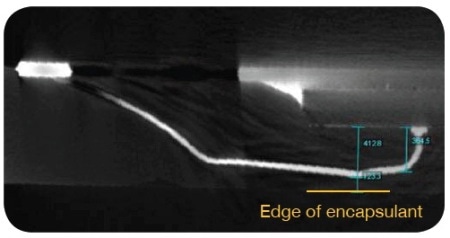
Figure 4. Virtual cross section of a single wire bond. Notice how it is possible to measure its shape and proximity to both the chip and the top of the plastic encapsulating material.
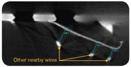
Figure 5. Virtual cross section enables measurement of proximity between multiple wires.
The high-resolution capability of the VersaXRM offers value for the characterization of new wire bonded devices, especially as wire bond diameters and pitches decrease and more complex architectures are introduced. The non-destructive nature of the VersaXRM offers the unique ability to perform multiple measurements on the same sample, such as before-and-after stress measurements. Moreover, in addition to 3D interconnect morphology, the microscope can simultaneously provide additional failure analysis information such as broken wires that cause opens and wires touching wires that cause shorts.

This information has been sourced, reviewed and adapted from materials provided by Xradia.
For more information on this source, please visit Xradia.