Engineers involved with the development and maintenance of complicated electromechanical systems are often faced with the challenge of linking the behaviour in one part of a system to control signals in another. Causality is the link between the cause and effect events. With a better insight into causality, engineers can understand the overall behaviour of electro-mechanical systems and take actions accordingly.
In order to perform daily measurement tasks, 2 or 4 channel oscilloscopes are often utilized. Conversely, since a mechanical system includes multiple sensors, control signals and actuators, four measurement channels are not adequate to detect the cause of an event.
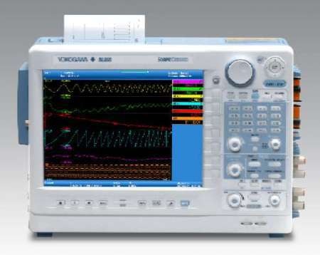
DL850 ScopeCorder
To overcome this issue, an instrument called DL850 ScopeCorder offers a suitable solution. The DL850 provides a familiar interface and also includes an assorted set of mechanical and electrical inputs. In order to link an adequate number of sensor and signals outputs, the DL850 can be configured with up to 128 measurement channels.
In addition, when compared to a standard oscilloscope, the DL850 provides advanced analysis tools to support causality analysis over extended periods of measurement.
Benefits of ScopeCorder
A DL850 ScopeCorder combines the benefits of a high-speed oscilloscope and a conventional data acquisition recorder. Owing to its large acquisition memory, this portable instrument is capable of capturing and analyzing long-term trends as well as microsecond events. This aspect makes it ideal for the measurement and fault analysis of almost any type of electro-mechanical system.

Figure 1. Multi-Channel Measurement on a DL850 ScopeCorder.
The input modules feature integrated isolation and signal conditioning to support the direct connection of high currents and high voltages of up to 1000 V. In addition, a range of sensors can be linked to dedicated input modules to determine temperature, torque, strain, vibration, frequency, rotation and other physical parameters.
The ability to combine these physical and electrical parameters makes the ScopeCorder suitable for analyzing actuators, inverters, control signals and transformers found in electromechanical systems.
Digital Signal Processing
On-board analysis tools such as waveform and cursor parameter measurement offer easy access to waveform data over extended periods of time. Now, with a "real-time mathematics" option, the DL850 functionality has been expanded. Here, a Digital Signal Processor (DSP) provides a set of functions, each specifically adopted to support a particular electromechanical application.
One such instance of a DSP function is the support for connecting a rotary encoder. This aspect allows the output signal of an encoder to be linked directly to the instrument sans the need for other signal conditioning. These signals are processed by the DL850, which in turn trends the encoder position as a waveform on the screen.
This could indicate a shaft driving the turbine of a wind powered generator or the shaft position of the bar roll of a printing machine. Connecting this position to the current, control signals and voltage in an electrical drive provides a better understanding about the system's behaviour.
Analysis of Load Variation on System’s Performance
An electromechanical system contains one or more electric motors, which range from the smallest to the largest motors. When an electric motor is working, load conditions may differ and the motor can take some time to adjust.
When a detailed assessment of an electric motor and its drive is required during these variable load conditions, the DL850 ScopeCorder can be used to measure and display the angle between the mechanical position of the motor and the fundamental current waveform of the motor drive utilizing Discrete Fourier Transform. The effects on system performance owing to load variation can thus be studied.
Another example of DSP capabilities includes the basic power measurement on one or three phase devices. With the help of the power graph, a cycle-by-cycle waveform of the active power can be displayed. This offers a better understanding about power behaviour during mechanical displacement cycles.
In order to determine the consumption of electrical power during a mechanical process, a "power integration" function monitors the power usage in real time as the mechanical process progresses.
Conclusion
To sum up, the ability to combine electrical parameters as well as physical parameters, such as temperature, torque, analogue sensor outputs, mechanical stress and vibration in one time-synchronized measurement, along with the use of powerful analysis functions, makes the DL850 an ideal tool to identify the cause of failures behind electro-mechanical systems.

This information has been sourced, reviewed and adapted from materials provided by Yokogawa.
For more information on this source, please visit Yokogawa.