The Nadcap program, developed by the Performance Review Institute, is designed to give an accreditation and quality assurance framework for a defined range of ‘special processes and products’ that are used within the Defense and Aerospace sectors. It was initially sponsored by Boeing and is currently adopted by all Western Aerospace Manufacturers.
Nadcap is becoming progressively important in the aerospace sector with accreditation regularly being requested by companies such as: Rolls Royce plc, GE Aviation, MTU, Bombardier, Turbomeca, Boeing, Snecma, Vought Aircraft Industries, Honeywell, Hamilton Sundstrand and Sikorsky Aircraft.
Manufacturers and end users must adhere to the requirements of the SAE Aerospace Standard Number AMS2750E. In this standard oven and furnace types are classified by the type of control instrumentation that they use and their temperature uniformity.
Carbolite GERO has substantial expertise in providing aerospace customers with oven and furnace systems built according to full AMS2750E and CQI-9 standards.
For furnace and oven systems to comply with AMS2750E, the following have to be defined:
- Class of temperature uniformity required – either Class 1, 2, 3, 4, 5 or 6
- Temperature range of compliance
- Temperature instrumentation type - either Type A, B, C, D or E
- Temperature Uniformity Survey (TUS) required either with charge or empty chamber
- Uniform zone required – define H x W x D
- System Accuracy Test (SAT) requirements
Nadcap Classes for Furnace / Oven Systems
| Class |
Uniformity |
| 1 |
± 3 °C |
| 2 |
± 6 °C |
| 3 |
± 8 °C |
| 4 |
± 10 °C |
| 5 |
± 14 °C |
| 6 |
± 28 °C |
For class 1 uniformity, ± 3 °C, the size of a furnace/oven chamber has to be considerably larger than the working volume. If a working volume of 600 mm x 600 mm x 600 mm is required, the recommendation is a chamber volume measuring about 800 mm x 800 mm x 800 mm.
Nadcap Product Instrumentation Types
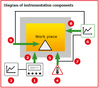
Control instrumentation type is defined as Type A, B, C, D, or E. The differences between these types are illustrated in the diagram below and relate to the number of recording thermocouples permanently installed in the work-space of the furnace, and the instrumentation employed to monitor these.

| |
Instrumentation components |
Type A |
Type B |
Type C |
Type D |
Type E |
| (1) |
Control instrument with temperature display |
X |
X |
X |
X |
X |
| (2) |
Control sensor |
X |
X |
X |
X |
X |
| (3) |
Control instrument recorder |
X |
X |
X |
X |
|
| (4) |
Over-temperature protection instrument |
X |
X |
X |
X |
|
| (5) |
Over-temperature protection sensor |
X |
X |
X |
X |
|
| (6) |
Multipoint chart recorder (or separate channel in control instrument recorder) |
X |
X |
X |
|
|
| (7) |
High temperature protection sensor connected to multipoint recorder |
X |
|
X |
|
|
| (8) |
Low temperature sensor connected to multipoint recorder |
X |
|
X |
|
|
| (9) |
Load sensor connected to multipoint recorder |
X |
X |
|
|
|