A recent article in the journal Infrared Physics & Technology involves the utilization of a moving mode of induction thermography for Non-Destructive Testing (NDT), for the analysis of thermal profiles of various holes and spacings.

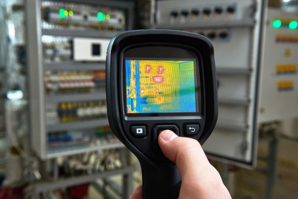
Study: Nondestructive inspection of holes with distinct spacing in plate using the moving mode of Induction Thermography. Image Credit: Dmitry Kalinovsky/Shutterstock.com
What is Non-Destructive Testing?
Non-destructive testing (NDT) is the method of analyzing, examining, or assessing substances, or elements for abnormalities or changes in attributes without compromising their workability. In other words, after the examination, the component can still be effectively used.
Other tests, contrary to NDT, are severe and are thus performed on a restricted sample size rather than the components that are physically being used. Modern NDT is now used in production, and in-service safety checks to regulate fabrication processes, lower costs, and maintain consistent performance levels.
Limitations of Conventional NDT Methods
The need for dependable NDT is growing in tandem with the industry's fast expansion. Traditional NDT technologies, including ultrasonic, radiographic, magnetic particle, and eddy current, continue to have limitations that restrict their future applicability for detecting microscopic superficial flaws.
Due to the exterior blind region impact, ultrasonic testing is not appropriate; radiographic examination has related safety problems based on radioactive contamination, and magnetic particle monitoring and eddy current analysis can only be utilized to identify failures on or just above exterior of metal materials. Given the limits of the abovementioned procedures, there is a need for creative ways that combine the benefits of two or more NDT techniques.
In this context, eddy current thermography (ECT) might be viewed as a novel potential methodology option due to characteristics such as noncontact, fast response, and visualization. Many studies have used stationary eddy current thermal imaging using a linear stimulation coil in the electricity, railway, and other domains.
What is Induction Thermography?
Electromagnetic bursts are used to create eddy currents in conductive materials in induction thermography, also known as pulsed eddy current thermography. Eddy currents create and radiate energy through leakage current. An infrared camera captures heating on the substrate exterior.
Surface fractures or concealed fissures closer to the surface generate regional variations in electrical charge concentrations that are evident in thermal imaging pictures. Sustained induction stimulation on moving metal bars was used to identify lengthwise fractures in the steel industry for the first time more than 20 years ago. Furthermore, the approach has been used to characterize surface adherence utilizing repeated scorching and to identify cracks in rotor blades employing cyclic activation.
Limitations of Induction Thermography
Researchers created a scanning electromagnetic thermography device to locate empty spaces as flaws in laminated composite plates utilizing the motional mode of eddy current thermography.
Further Reading on AZoM: Ground Penetrating Radar Applied to Concrete Specimens
While the bulk of the preceding investigations have concentrated on defect identification in motional mode, the preceding detection performance is essentially similar in static mode. Furthermore, minor defect identification in the moving detection mode of eddy current thermography remains a difficulty.
In the study, currents of 200A and 238 kHz were employed for inductive stimulation for both static and dynamic studies. This work's specimen is referenced as 20# steel. This metal sheet was composed of low carbon steel and had a thickness of 15mm. It had 7 fabricated hole flaws.
Experimental Results
Since it reaches the peak of the first derivatives, initial heating (t = 10ms) was designated as the very first key point. It was discovered that the temperature profile is connected to defect separation and that temperature rose as the separation distance decreases (TH2>TH4 >TH6 >TH7).
Furthermore, when the band spacing is considerable (S3>S2), the temperatures of the separation were lower (TS3<TS2); when the band spacing was equal (S1=S2), the temperatures on the side with the shorter defect separation was greater (TS1>TS2).
In the terms of dynamic examination, the border of the fault gets increasingly fuzzy as the operational speed increases. The resolutions of the four faults were at their peak near the conclusion of the treatment, with each defect's resolutions displaying a declining trend during the thermal dissipation stage.
Furthermore, it was shown that speed has a vital effect on thermal gradients in different places. Temperature-based features reduced proportionally as speed rose. This revealed that in both situations, separation was the most important element influencing linear patterns.
To conclude, the comparable heating model was discovered to be an efficient technique of connecting dynamic and static monitoring. According to the findings, there was an inverse association between screening velocity and temperature-based characteristics. However, the mechanism linking stationary and motional modes has to be researched further in future research.
Further Reading
X. Zhang, J. Peng, K. He, X. Gao. Nondestructive inspection of holes with distinct spacing in plate using the moving mode of Induction Thermography. Infrared Physics & Technology (2022), Available at: https://www.sciencedirect.com/science/article/pii/S1350449522000263?via%3Dihub
Disclaimer: The views expressed here are those of the author expressed in their private capacity and do not necessarily represent the views of AZoM.com Limited T/A AZoNetwork the owner and operator of this website. This disclaimer forms part of the Terms and conditions of use of this website.