Vascularization has a crucial function in healing and regeneration since endothelial cells play a large part in organogenesis, tissue development, and maintenance. A tissue-specific, exceptionally ordered, and hierarchically organized network is a hallmark of physiological vascularization.
Bioengineering techniques can aid in inducing regeneration when insufficient vascularization prevents healing. To efficiently deliver nutrition, signaling molecules, oxygen, and metabolites, rapid vascularization is essential. In larger tissue or organ contexts, each of these essential activities guarantees cell viability and prevents the formation of a necrotic core. Unfortunately, in vitro methods still struggle to replicate the physiological intricacy of tissues and microvasculature.
Controlling a specific vascularization patterning process appears to be crucial for bioengineering physiological supply and ensuring overall tissue performance. To create functioning 3D-vascularized constructions, many different methods have been devised. Human mesenchymal stromal cells (hMSCs) are the most popular supporting cell type, even though human umbilical vein ECs (HUVECs) are commonly used for such techniques. Despite the ability to manipulate vessel geometry provided by the method of creating prefabricated vessels with endothelial lining, it is still difficult to replicate the intricacy of naturally occurring microvascular networks.
Existing 3D bioprinting techniques that attempt to promote endogenous microvascular self-assembly create microvascular networks with little control over their precise patterning.
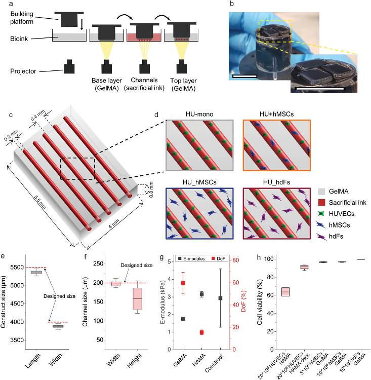
Experimental setup of the 3D-bioprinted vascularized constructs. a) Schematic representation of the printing process with the projection-based stereolithography 3D bioprinting using a multi-material, layer-by-layer printing approach. Hollow channels were generated by enzymatically degrading the sacrificial ink methacrylated hyaluronic acid (HAMA, red) in combination with methacrylated gelatin (GelMA, bulk material, grey). b) Image of constructs after printing on top of the building platform. Scale bars: 10 mm. c) Model of the designed construct with five parallel channels (realized by the printing of sacrificial ink, red) surrounded by a hydrogel (GelMA, grey). d) Illustration of the different investigated cellular arrangements. Printing fidelity of the stereolithographic 3D bioprinter was determined by comparing e) the measured printed hydrogel construct size in length and width and f) the measured channel size in width and height to the designed size in the CAD model (dashed red line, n = 11). g) Both bioink materials and the printed construct properties were characterized by their Young's modulus of photopolymerized GelMA (n = 9) and HAMA (n = 3) and their degree of functionalization (DoF) (HAMA n = 2, GelMA n = 4). The effective E-modulus of printed constructs was also measured using a nanoindentation method (Piuma Optics11, n = 4). h) Cell viability was determined for each cell type at respective cell concentration and in the respective bioink. HUVECs were printed with 20 × 106 cells mL−1 in HAMA and measured encapsulated in the photopolymerized ink as well as after degradation of the HAMA with the enzyme hyaluronidase (Hase, HAMA degr.). hMSCs and hdFs were printed in 7% (w/v) GelMA at different cell concentrations (n = 4). Image Credit: Orellano, I et al., Advanced Functional Materials
About the Study
In this study, the authors discussed a bioengineering technique to control the creation of microvascular structures and to direct the cellular self-assembly of supporting and endothelial cells within a multi-material stereolithographic 3D bioprinting concept. Controlled cell deposition in an enzymatically degradable or a non-degradable substrate produced bioengineered vascularized constructions. The distribution, network direction, branching behavior, vessel length, indications of vascular stabilization, formed lumen, and interconnected vascular network, including anastomosis, of the microvascular structures in vitro were all controlled.
The team employed cellular and geographical signals to show the potential of the proposed biofabrication and to control the establishment of microvascular networks, enabling the creation of distinctive yet accurately vascularized constructions. The proposed cutting-edge method of regulated microvascular production might be crucial in creating vascularized implants or in vitro testing models. The proposed bioengineering method integrated the aforementioned approaches, allowing for the control of the geometry of microvascular structures through the use of a multi-material stereolithography 3D bioprinter and an avant-garde biomaterial system.
The researchers illustrated that within this framework, the interaction between hMSCs and human dermal fibroblasts (hdFs), supportive cell types, and the vasculogenic and angiogenic behavior of HUVECs was investigated. As a result, by modifying cell type and location, this study constituted a comprehensive investigation of the development and modification of microvascular architectures by cellular self-assembly. The results showed that an endothelial lining could be directly printed and self-assembled posteriorly, and they also showed how cell type and position could control the development of self-assembled microvascular structures inside the construct. Specific compartments were designed for the development of microvascular structures.
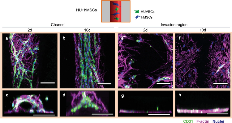
Cellular arrangement of HUVECs and hMSCs printed in proximity in the channel (Group HU+hMSCs). a) Representative confocal images of the channel with HUVECs (green) forming vascular structures as early as 2 days post printing. hMSCs (magenta) in proximity spanning in between newly forming vascular structures. b) Representative confocal image after 10 days showing more mature microvascular structures, with a constant diameter and hMSCs aligning with the strongly oriented vascular structures along the channel direction. c) Representative front view image of the channel 2 days after printing with cells initially attach to channel surface. d) Representative front view image of the channel 10 days after printing completely filled by cells. e,f) Representative images of the invasion region 2 and 10 days after printing with little immigration of HUVECs, but strong immigration of hMSCs from the channel. g,h) Front view reconstructions of the invasion region 2 and 10 days after printing with no cells penetrating the bulk material. Samples were stained for CD31 (HUVECs, green), nuclei (blue) and F-actin (hMSCs and HUVECs, magenta). Scale bars: a,b,e,f) 50 µm, c,d,g,h) 200 µm. Image Credit: Orellano, I et al., Advanced Functional Materials
Observations
The average methacrylation degree of GelMA was 59.8 ± 9.6%, which was within the range of the degree of functionalization (DoF) described for the ideal stiffness and pore size for cell viability, migration, proliferation, and spreading as well as creating cell-cell interactions. The 0.2 mm in diameter by 5.5 mm in length endothelialized bioprinted tube had an open lumen for potential perfusion. Even though HUVEC coverage was only roughly half as great when hdFs were used in the cultivation, the cell coverage after 2 days showed that hdFs moved into the channel more quickly than hMSCs.
In line with the bulk properties, a local stiffness of 2.9 ± 1.7 kPa was observed. The half-time of relaxation (τ1/2), had a value of 1.7 ± 0.4 s. 7% w/v GelMA had a mean E-modulus of 1.75 ± 0.07 kPa according to material tests, while 1.5% w/v HAMA had a mean E-modulus of 3.15 ± 0.16 kPa. The bioengineering technique that was used to create a bioprinted, patterned vascular construct enabled in-depth analysis and management of neovascularization and angiogenesis.
By adjusting the bioprinting set up, the proposed technology enabled the development of macrovascular channels by an endothelial lining as well as the formation of programmable microvascular structures by cellular self-assembly processes. These quickly formed, well-defined vascular patterns were either strongly interconnected microvascular networks or completely oriented along the channels. By altering the type and location of the supporting cells, vascular structures could be formed and their formation controlled. Incorporated cells showed signs of maturation and stabilization, as well as the ability to build interconnected vascular networks via angiogenesis and anastomosis within a few days of cultivation. They also showed the ability to form microvascular structures with the lumen.
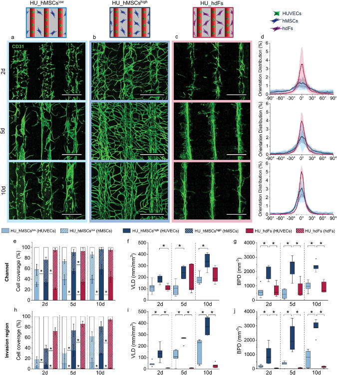
Regulation of microvascular structure formation by altering cell placement, concentration of hMSCs in the bulk, and cell type. Direct comparison of the group a) HU_hMSCslow (light blue), b) HU_hMSCshigh (dark blue), and c) HU_hdFs (magenta) visualized by maximum projection of representative confocal images stained for CD31 (green) for 2, 5, and 10 days post printing. Scale bars: 500 µm. d) Cell orientation analysis within the channel of 2, 5, and 10 days post printing (from top to bottom). Cell coverage (HUVEC coverage = full bar, hMSC/hdF coverage = patterned bar, empty/uncovered area = white bar)), VLD and BPD of the vascular structures in the e–g) channel and in the h–j) invasion region for 2, 5, and 10 days. Statistical significance via Mann–Whitney test (two sided), *p < 0.05, n = 5. Image Credit: Orellano, I et al., Advanced Functional Materials
Conclusions
In conclusion, this study elucidated that by engineering different spatial arrangements of cells to control cell-cell migration, interaction, and proliferation, the quantity, length, orientation, and branching behavior of the forming vascular structures could be controlled. The establishment of distinct yet precise vascularization was made possible by the proposed method of fusing the strength of cellular self-assembly with spatial control of vessel formation. To simulate the stiffness of real soft tissue, such as the brain, spleen, skin, and muscles, the materials' E-moduli were chosen in a low range of 1-4 kPa.
The authors mentioned that the implementation of the observed results might make it easier to create novel tissue engineering techniques with vascular architectures that are better suited to the needs of the tissue.
References
Orellano, I., Thomas, A., Herrera, A., et al. Engineering Vascular Self-Assembly by Controlled 3D-Printed Cell Placement. Advanced Functional Materials (2022). https://onlinelibrary.wiley.com/doi/10.1002/adfm.202208325
Disclaimer: The views expressed here are those of the author expressed in their private capacity and do not necessarily represent the views of AZoM.com Limited T/A AZoNetwork the owner and operator of this website. This disclaimer forms part of the Terms and conditions of use of this website.