Elemental identification and particle count answer two key questions in oil analysis: "how many?" and "where is it coming from"?. These two measurements are the most critical in any machine condition monitoring application.
Particle count is often a pre-screen for conducting RCA using SEM/EDX, XRF and in some cases ferrography with current technologies. These techniques have proven to be expensive, time consuming and very labor intensive.
Typical monitoring of the machine condition is done by quantifying the number, size and elemental composition of wear particles produced at the extremities of lubricated machine parts. The size and quantity of these wear particles has a direct correlation to a benign versus an abnormal wear state as shown in Figure 1.
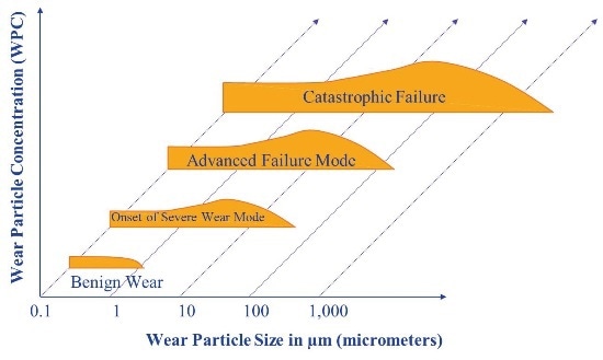
Figure 1. Progression to failure
Existing Machine Failure Measurement Techniques
Particle Count
The severity of a wear situation is indicated by the particle count and the transition from small to large particles can easily be detected. Particle count is normally done using one of the following techniques:
- Laser light blockage
- Direct imaging
- Pore blockage
Atomic Emission Spectroscopy
Atomic emission spectroscopy by either rotating disc electrode (RDE) or inductively coupled plasma (ICP) is used for elemental identification of wear particles. Both these techniques are limited when it comes to identifying large particles. Hence other techniques have been developed that include Rotrode Filter Spectroscopy (RFS) and acid digestion.
X-Ray Fluorescense (XRF)
XRF is a common technique that quantifies individual chemical elements in used oil samples. Samples are typically analyzed by taking an x-ray of a small oil sample (1-2ml) in a cup.
Ferrography and Filter Patch Analysis
More advanced ferrography techniques for substrate preparation also identify ferrous from non-ferrous metals and crystalline from non-crystalline materials. The biggest downside to performing ferrography is that it is time consuming and requires an expert to perform the analysis.
SEM EDX
The SEM EDX technique is used for studying particles visually at very high magnifications and performing spot elemental analysis on the particle using an EDX device. The instruments are expensive and the technique involves some sample preparation, such as applying a conductive coating to the sample to help increase resolution.
A New Technique - Filtration Particle Quantification Combined with EDXRF
This unique system design features interpreting root cause analysis and machine failure by using a two-step process combining a modified pore blockage technique with an XRF analyzer.
Figure 2 shows the tower which encompasses the FPQ and XRF device in the overall oil monitor system. The figure also shows the filter being inserted into the XRF. This relatively quick process can screen out samples with high particle counts and perform a complete 13 element XRF analysis on the resultant sample filter.
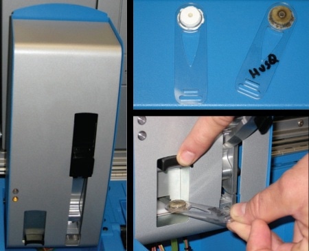
Figure 2. FPQ and XRF tower assembly
Combined Particle Quantifier (FPQ) and XRF Device
The modified pore blockage technique has been termed “Filtration Particle Quantification” or FPQ. The FPQ uses constant flow by driving a 3ml oil sample using a syringe through a polycarbonate filter with ~30,000 4µm diameter holes.
The resulting pressure drop across the filter measured with reference to atmospheric pressure is used for particle quantification greater than 4µm up to ~1million particles/ml. A modified filter design is used when compared to a conventional pore blockage instrument. This new patent pending dual dynamic design allows a much greater particle count range (x50) beyond the point where particle swapping and saturation occurs as shown in Figure 3.
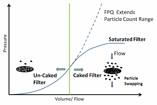
Figure 3. FPQ filter vs. conventional pore blockage filter
On analysis completion, the filter passes from the FPQ to the XRF device. The FPQ and XRF are closely linked in terms of calibration due to the particle swapping phenomenon.
FPQ/XRF Device Case Studies
These case studies show how the FPQ/XRF device correlates to existing analytical techniques for measuring particles in various real word applications.
FPQ and X-Ray Correlation to Established Measurement Techniques
The following data set from a series of marine diesel vessels was used to evaluate the FPQ and XRF technology. Samples were analyzed on the FPQ device and XRF and were shown to correlate to LaserNet Fines® and acid digestion using the ICP.
A model using an assumed wear particle size aspect ratio and particle mass was used to further correlate the aggregate elemental concentration on the FPQ filter using the LaserNet Fines® and XRF data. Figure 4 and Figure 5 show how the FPQ and XRF correlate to the LaserNet Fines® direct imaging particle counter.
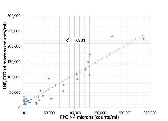
Figure 4. LaserNet Fines® vs. FPQ (counts/ml > 4µm)
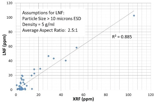
Figure 5. LaserNet Fines® vs. XRF – total ppm
XRF vs. Acid Digestion
The data in Table 1 shows a selection of marine samples analyzed on the ICP before and after acid digestion.
Table 1. Differential Acid Digestion Sample Result (Sample E=10-1151, Sample F=10-1149)
| |
Before Acid Digestion - ICP (ppm) |
After Acid Digestion - ICP (ppm) |
| Sample |
A |
B |
C |
D |
E |
F |
A |
B |
C |
D |
E |
F |
| Ag |
0 |
0 |
0 |
0 |
0 |
0 |
0 |
0 |
0 |
0 |
0 |
0 |
| Al |
0 |
0 |
0 |
10 |
10 |
21 |
0 |
0 |
0 |
0 |
13 |
28 |
| Cr |
6 |
0 |
0 |
0 |
6 |
7 |
6 |
0 |
0 |
0 |
6 |
8 |
| Cu |
0 |
0 |
0 |
0 |
11 |
11 |
0 |
0 |
0 |
0 |
10 |
10 |
| Fe |
10 |
7 |
0 |
0 |
33 |
67 |
11 |
10 |
0 |
0 |
35 |
86 |
| Mo |
0 |
0 |
0 |
0 |
0 |
0 |
0 |
0 |
0 |
0 |
0 |
0 |
| Ni |
0 |
0 |
0 |
0 |
0 |
0 |
0 |
0 |
0 |
0 |
0 |
0 |
| Pb |
0 |
0 |
0 |
0 |
0 |
0 |
0 |
0 |
0 |
0 |
0 |
0 |
| Sn |
0 |
0 |
0 |
0 |
0 |
0 |
0 |
0 |
0 |
0 |
0 |
0 |
| Ti |
0 |
0 |
0 |
0 |
0 |
0 |
0 |
0 |
0 |
0 |
0 |
0 |
| V |
0 |
0 |
0 |
0 |
0 |
0 |
0 |
0 |
0 |
0 |
0 |
0 |
| Total ppm |
16 |
7 |
0 |
10 |
60 |
106 |
17 |
10 |
0 |
0 |
64 |
132 |
This method is commonly known as differential acid digestion. Figure 6 shows how the differential ICP results (large particles) for samples E and F compare to the XRF data for the same samples. The large particle portion correlates very well (within 3ppm) to the filtered XRF results as seen in Figure 6.
Figure 7 shows the difference in ppm between the ICP and XRF readings for Fe and Al in Sample F.
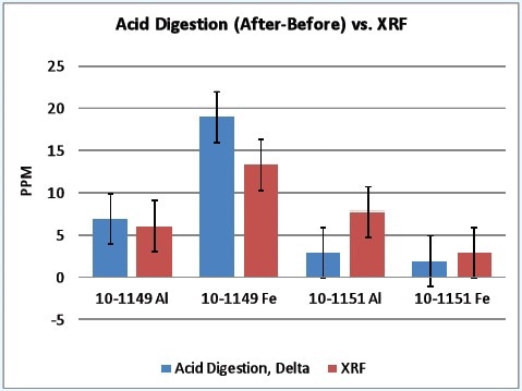
Figure 6. Differential ICP vs XRF (Sample E=10-1151, Sample F=10-1149)
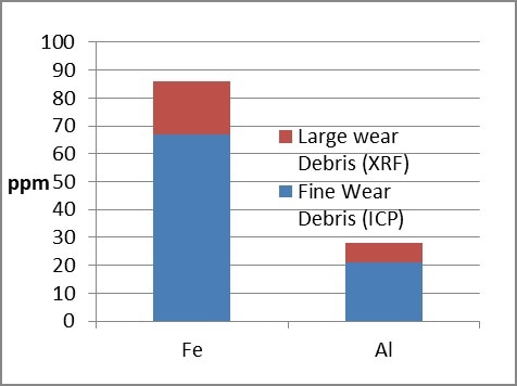
Figure 7. Typical ratio of large to small particles observed between XRF and ICP
PPM (mass) vs Particle Concentration (quantity) on the FPQ Filter
Based on iron density, it will take approximately 100 particles in 1ml of oil to raise the elemental concentration by just 1ppm. In this example, the Fe and Al wear particles are most likely caused by cylinder/piston wear. This is a common failure mode in the application and shows how the XRF is able to identify root causes of problems.
Wear Progression to Failure
When a machine enters an abnormal wear mode there is always an increase in the size and production of severe large wear particles.
For larger particles measured by FPQ and XRF, a static limit applies after the system reaches equilibrium. This is demonstrated in Figure 8.
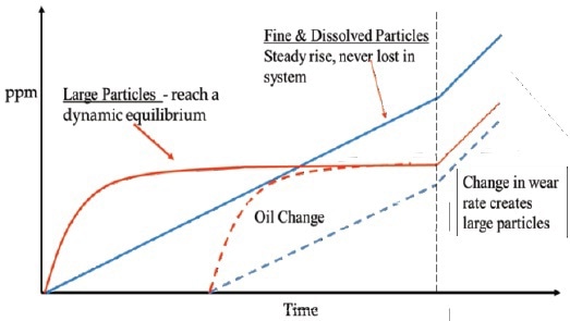
Figure 8. Behavior of large vs fine particles
The FPQ can handle a wide range of applications with relatively high wear rates (up to 1.0 million p/ml). As expected, the particle count on the FPQ correlates well with direct imaging particle counting (Figure 9).
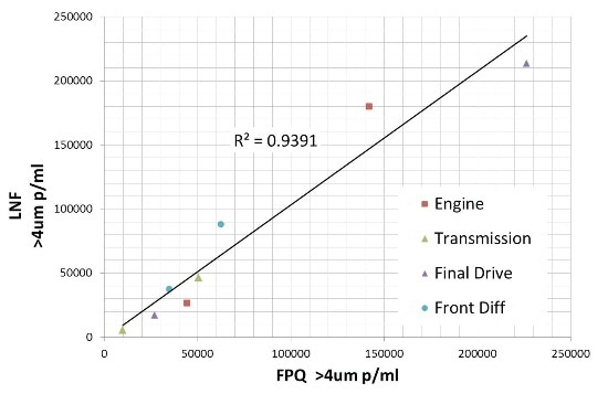
Figure 9. FPQ vs LaserNet Fines®, normal and abnormal wear in different applications
In addition,the elemental XRF readings can differentiate between low wearing systems and more critical high wearing systems. This data shows that it is possible to make a recommendation on the root cause of the increased wear rates based on a material map of the lube system.
This data set also demonstrates a unique advantage that the FPQ has when analyzing emulsions and other sample types that contain “phantom” particles included in the overall particle count.
Water and other liquids pass through the polycarbonate filter pores and the results are unaffected. Sample E3 contains a significant amount of free water ingestion that produced a highly elevated particle count reading on the LaserNet Fines®. The real particle count in this sample was only ~ 31kp/ml and the elemental level was low.
Conclusion
The FPQ, with its patent pending dual dynamic filtration system, handles a wide range of lubricant applications with varying wear levels. The particle count using the FPQ filter correlates with existing direct imaging particle counting. T
he subsequent elemental concentration from the FPQ filter using XRF analysis correlates well with ICP differential acid digestion, demonstrating that the methodology is valid. This methodology eliminates many of the problems associated with other techniques such as particle size detection and the impervious nature of many used oils found in heavy duty industrial applications.

This information has been sourced, reviewed and adapted from materials provided by AMETEK Spectro Scientific.
For more information on this source, please visit AMETEK Spectro Scientific.