This article advocates for enhanced testing of in-service lubricants to transition from unplanned repairs and downtime to scheduled, planned maintenance. By leveraging oil analysis, the aim is to improve reliability, planning, and scheduling through more comprehensive testing, with a particular focus on large wear particle analysis.
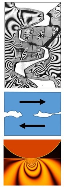
Image Credit: AMETEK Spectro Scientific
In-service lubricant analysis serves both proactive and predictive roles. Proactive measurements—such as particle count, water content, glycol levels, viscosity, and acid number—concentrate on contamination control and ensuring the lubricant's suitability. These proactive checks, combined with other precision maintenance efforts, contribute to extended equipment life and enhanced reliability.
Predictive analysis, particularly large wear debris analysis, focuses on non-intrusively assessing the rate, mechanism, and severity of abnormal wear. This approach aims to minimize unscheduled repairs by facilitating planned maintenance.
Predictive wear particle analysis complements other diagnostic tools, such as vibration analysis for gear and antifriction bearing failures, motion amplification for bending failures, and turbomachinery protection systems for wiped plane bearings.
Large wear debris analysis targets metal particles—such as iron, copper, lead, and tin—ranging from five microns to several hundred microns. Severe sliding and fatigue wear debris predominantly consist of these larger particles.
Tools like ferrous density measurements and X-ray fluorescence are critical for monitoring severe sliding and fatigue in gears, shafts, antifriction bearings, and plane bearings. Given that equipment repairs and component replacements often require several months of advance planning, this article emphasizes the importance of addressing severe sliding and fatigue wear processes.
Recommendations for improving repair planning include reviewing repair histories and root cause failure analysis (RCFA) data, identifying and sampling lubricants from components prone to adhesion and fatigue, and increasing both the frequency and quality of testing and analysis. Tracking progress towards reducing unplanned repairs through scheduled maintenance is also essential.
Abnormal Wear at its Worst
Severe sliding, rolling fatigue, and bending fatigue are failure mechanisms that drastically reduce the lifespan of machine components, with damage from each mechanism being both cumulative and progressive. Wear debris generated from these mechanisms provides insights into the damaged component, the causes of damage, and the extent of failure progression.
Severe sliding wear is depicted in the images labeled “Adhesion” in Figure 1.
This type of wear occurs when the lubricant film between moving components is compromised, leading to metal-to-metal contact. The resulting shear and friction produce intense heat, melting, and smearing of the metal surfaces.
Inadequate lubrication, where the necessary hydrodynamic or elastohydrodynamic film is disrupted while the machine is under load, is a common cause of severe sliding wear. Factors contributing to inadequate lubrication include misapplication, low operating speed, excessive load, and low viscosity.
Rolling fatigue, also known as Hertzian fatigue, is illustrated in the images beside “Fatigue” in Figure 1.
This failure mechanism involves subsurface work hardening due to the high loads and rolling compression experienced by antifriction bearing rollers, raceways, and gear teeth pitch lines. Bending fatigue, not depicted in this figure, is characterized by the propagation of tension cracks typically originating from stress concentrations such as tight fillets.
The processes of adhesion, rolling fatigue, and bending fatigue are significantly accelerated by additional factors such as general corrosion, stress corrosion, galvanic corrosion, erosion corrosion, and spark erosion.
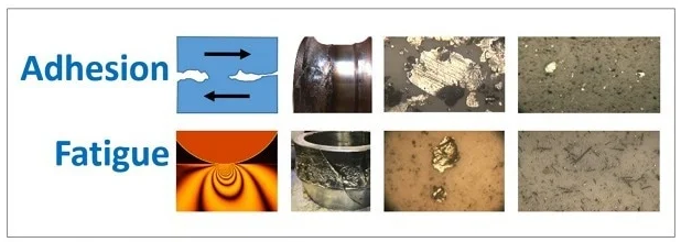
Figure 1. Severe sliding adhesion and rolling fatigue failure mechanisms. Image Credit: AMETEK Spectro Scientific
Severe Sliding and Fatigue Particles Range from 10 µm to Hundreds of Microns
Adhesion and fatigue wear mechanisms generate large wear debris that falls into the severe, advanced, and catastrophic size ranges, as depicted in Figures 2 and 3. These figures categorize wear particle sizes into benign, severe, advanced, and catastrophic wear types.
Both adhesion and fatigue are abnormal wear processes that produce particles too large to be effectively analyzed using optical emission spectroscopy.
Abnormal wear debris from abrasion, adhesion, and fatigue consists of large particles containing base metals. Microspall particles typically range from 10 µm to 50 µm, while laminar particles and chunks can vary from 50 µm to several hundred microns. Optical emission spectroscopy is not effective for detecting such large particles.
The green-to-yellow-to-red bar labeled “Prediction” and “Protection” in Figure 2 illustrates the importance of collecting lubricant samples during the prediction phase. This proactive sampling allows for repairs to be planned and executed before reaching the catastrophic stage, where unplanned repairs and downtime become unavoidable.
Figures 2 and 3 also show various instrument types and their measurement capabilities for different wear particle size ranges, emphasizing the need for appropriate tools to effectively monitor and manage wear.
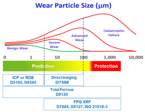
Figure 2. Wear particle analysis for benign, severe, advanced and catastrophic wear debris. Image Credit: AMETEK Spectro Scientific
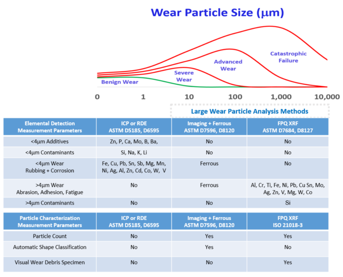
Figure 3. Elemental analysis and wear particle characterization measurement parameters. Image Credit: AMETEK Spectro Scientific
Severe Sliding and Fatigue in Gears and Rolling Element Bearings
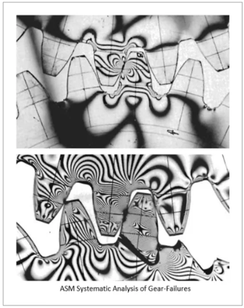
Figure 7. Gear tooth stress. Image Credit: AMETEK Spectro Scientific
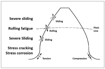
Figure 8. Gear tooth wear. Image Credit: AMETEK Spectro Scientific
Rotating, reciprocating, and articulating machinery—such as pumps, motors, compressors, gearboxes, fans, couplings, rolls, and screens—are susceptible to severe sliding adhesive wear, rolling fatigue wear, and fatigue cracking. These wear mechanisms often develop in progressive stages, from incipient defects to increasingly severe conditions.
This article describes these stages of wear, categorized as benign, severe, advanced, and catastrophic, based on the size and quantity of metal wear debris.
Severe Sliding Adhesive Wear occurs when there is abnormal metal-to-metal contact between moving components. Typically, sliding motion is supported by a hydrodynamic lubrication film, approximately 100 µm thick, that separates the components.
Localized adhesive wear can happen due to extreme loading, low speed, inadequate lubrication, low-viscosity oil, or improper lubrication application. It is also common when rollers skid rather than roll due to a breached elastohydrodynamic lubricant film, which is only about 1 µm thick.
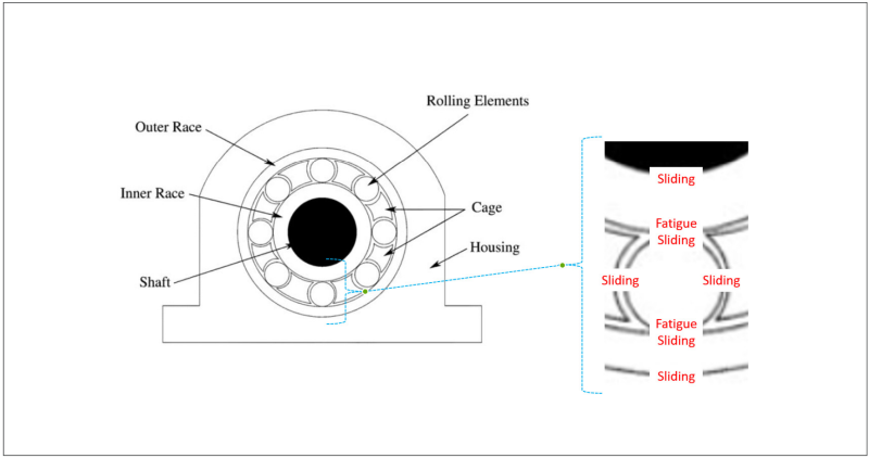
Figure 9. Severe sliding and fatigue in antifriction bearings. Image Credit: AMETEK Spectro Scientific
Rolling Fatigue Wear results from cyclic rolling compression loads, such as those experienced between roller and raceway or gear teeth near the pitch line. Figure 6 illustrates the stress patterns on gear teeth caused by load transfer from tooth to tooth.
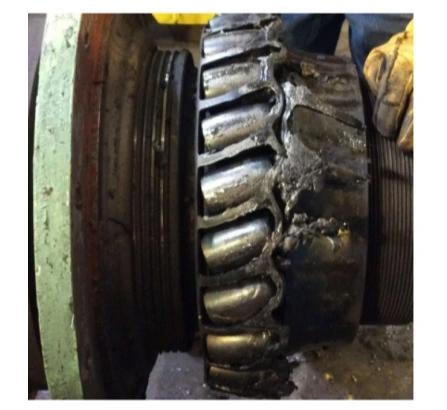
Figure 10. Queen roll bearing after failure due to inadequate lubrication between cage and rollers. Image Credit: AMETEK Spectro Scientific
Figure 4 depicts the relative movements between adjacent gear teeth. Normal rolling compression load transfer is supported by an elastohydrodynamic lubricant film (approximately 1 µm thick) near the pitch lines of the gear teeth. Above and below the pitch line, movement between adjacent teeth involves sliding supported by a hydrodynamic lubricant film (approximately 100 µm thick).
Inadequate lubrication can lead to severe sliding wear, particularly above the pitch line (addendum) and below the pitch line (dedendum). Common causes of inadequate gear lubrication include insufficient oil levels, no oil, low speed, excessive loading, low viscosity, and the absence of anti-wear extreme pressure (AW-EP) additives.
Rolling Fatigue Wear is prevalent near the pitch line of gears, where the rolling compression load is highest. The lower right image in Figure 1 depicts long, slender needle-shaped wear debris typical of rolling fatigue in gear teeth.
Tensile stress cracking and stress corrosion cracking result in fractured gear teeth, as depicted in Figure 4's lower image. The most common type of fatigue breakdown is a root fillet fracture. The crack starts at the root fillet on the tensile side of the tooth and gradually progresses to a full fracture along or across the tooth.
Severe sliding and rolling fatigue are common reasons for antifriction bearing failure. Figure 6 shows a roller bearing from the center to the outside. Looseness between the inner race and the shaft might lead to catastrophic sliding failure. Inadequate lubrication can cause rollers to skid rather than roll in raceways.
Even with a flawless elasto-hydrodynamic lubricating coating (about 1 µm thick), highly loaded rolling components and raceways will still experience fatigue wear.
A hydrodynamic lubricating coating (about 100 µm thick) is required for relative motion between the cage and rollers. Figure 4 depicts a queen roll bearing that failed owing to inadequate lubrication between the cage and rollers.
Large Wear Debris Analysis for Gears, Shafts, Roller Bearings, and Plane Bearings
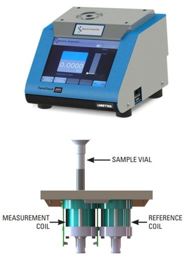
Figure 11. Total ferrous PPM measurement of in-service oil and grease. Image Credit: AMETEK Spectro Scientific
To improve reliability, it is crucial to sample lubricants from multiple points, with a particular emphasis on detecting large wear particles.
For machinery with circulating oil systems, samples should always be taken from the return line before they mix with the main oil reservoir. This is because around 5 % of the oil flows through the machinery components and carries back significant wear debris for analysis.
Whenever possible, collect samples before a 20:1 dilution occurs. For non-circulating oil systems, adhere to best practices for sampling in active zones.
When sampling and testing grease lubricants from bearings, use a ferrous PPM analyzer according to ASTM D8120 standards. Regular sampling is advised, particularly for bearings susceptible to abrasion and fatigue, whenever they are opened for maintenance or repair. Diesel fleets typically collect oil samples only during changes, but it is beneficial to apply similar practices for grease-lubricated bearings to monitor total ferrous PPM.
Understanding the metal elements resulting from abnormal wear and fatigue is key to preventing unforeseen repairs. This requires sampling, testing, and analyzing large wear particles to detect, trend, and predict potential issues.
Common metals found in wear debris are detailed in Figure 12, with large ferrous PPM being a major indicator for most industrial machinery like gears and bearings, followed by large copper PPM.
Wear debris from wiped plane bearings, such as journals and bushings in large motors and turbomachinery, often includes "yellow metal" or "white metal" alloys, primarily composed of copper, lead, or tin, and occasionally containing a small amount of antimony.
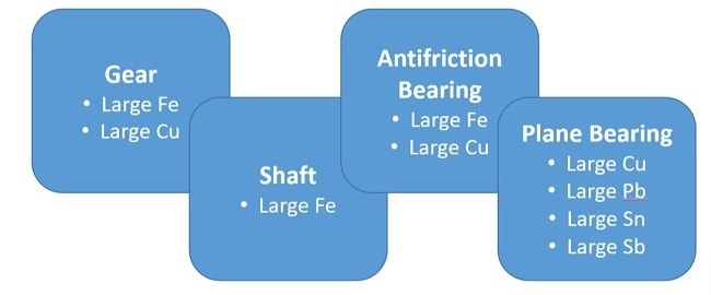
Figure 12. Common wear debris metals for gear, shaft, antifriction bearing, and plane bearing components. Image Credit: AMETEK Spectro Scientific
Conclusions
Pumps, motors, compressors, gearboxes, fans, couplings, rolls, screens, and other rotating, reciprocating, or articulating machinery are susceptible to various forms of wear, including sliding adhesive wear, rolling fatigue wear, and fatigue cracking.
Typically, defects evolve through distinct stages of severity, which can be categorized as benign, severe, advanced, and catastrophic based on the size and quantity of metal wear debris produced.
At its most severe, abnormal wear manifests through significant sliding, rolling fatigue, and bending fatigue, which dramatically reduce the operational lifespan of machine components.
This damage is both cumulative and progressive, with wear debris offering critical insights into the damaged components, the nature of the damage, and the progression of failure. Particles resulting from severe sliding and fatigue typically range from 10 microns to several hundred microns in size.
Analysis of large wear debris is predictive, aiming to measure the rate, mechanism, and severity of abnormal wear without intrusive methods. The objective is to transition from reactive, unplanned repairs to proactive, scheduled maintenance.
Predictive wear particle analysis enhances traditional methods, such as vibration analysis for detecting gear and antifriction bearing failures due to rolling fatigue and severe sliding. It also complements motion amplification for identifying bending failures and turbomachinery protection systems for monitoring wiped plane bearings.
In large wear debris analysis, metal particles (iron, copper, lead, and tin) are examined across sizes from five microns to hundreds of microns. Severe sliding and fatigue wear predominantly produce large wear debris.
Techniques such as direct imaging, ferrous density measurement, and X-ray fluorescence are essential tools for monitoring wear in gears, shafts, antifriction bearings, and plane bearings.

This information has been sourced, reviewed and adapted from materials provided by AMETEK Spectro Scientific.
For more information on this source, please visit AMETEK Spectro Scientific.