Sponsored by HORIBAJun 12 2018
Fluorescence Spectroscopy is based on the number of key principles and applications. These are outlined below.
What Is the Jablonski Diagram?
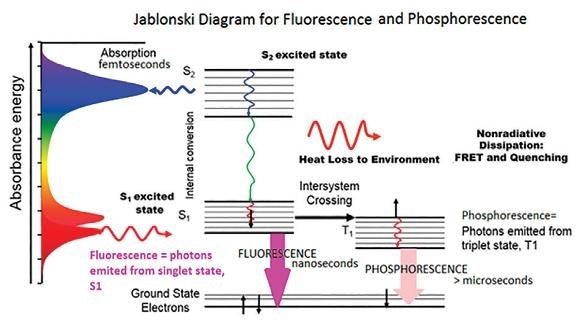
The Jablonski diagram was developed in 1933. It is a well respected schematic of the transition of the electronic state of a molecule during the phenomenon of fluorescence. In the diagram below, the left axis highlights increasing energy where a normal fluorescent molecule possesses an absorbance spectrum. This absorbance spectrum illustrates the wavelengths or energy where the molecule will absorb light.

Figure 1. The Jablonski Diagram of molecular absorbance and fluorescence
If incident light is at a wavelength at which the molecule is able to absorb the photon, then the molecule itself is excited from the electronic ground state to a higher excited state. This is shown as S2 on the diagram.
During this process, electrons go through an internal conversion as they are affected by heat loss from the environment and vibrational relaxation. Next, a photon is emitted from the lowest lying singlet excited state. This is the fluorescence.
During the more common occurrences of fluorescence, photons are emitted at higher wavelengths than the photons that are absorbed.
This diagram is critical in the understanding of fluorescence. As can be understood from examining the diagram itself, measurement of a fluorescence spectrum involves examining the intensity at which a molecule emits, the energy at which it emits and the time that the molecule spends in its excited state. The latter of these measurements is known as the fluorescence lifetime.
These observables can be affected by a whole range of factors such as quenching by other molecules, energy transfer from other molecules, pH, local polarity, temperature, binding or aggregation. Being able to understand the underlying mechanisms of each of these interactions can offer up real insight into exactly what is being seen when viewing a change in the fluorescence spectra or lifetime.
Two non-radiative deactivation processes exist that are in direct competition with fluorescence. These are intersystem crossing from the excited singlet to the triplet state and the internal conversion from the lowest singlet to the ground state.
The former of these two processes leads to a particular phenomenon known as phosphorescence.
What Is a Fluorescence Lifetime?
At its most fundamental, a molecule’s fluorescence lifetime can be understood as the average length of time that it spends in the excited state.

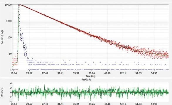
Figure 2. Fluorescence lifetime decay of fluorescein (red), instrument response (blue) and fit (green). Error residuals are shown in lower graph. Here, the lifetime is approximately 4.0 ns.
This largely depends on the type of molecule in question and its local environment. The molecule’s excited state decays in an exponential manner as highlighted by the equation below.
Measuring fluorescence lifetime rather than a standard intensity measurement offers particular advantages, specifically that it is an absolute measurement rather than the relative steady state measurement which is only able to provide a time averaged signal.
I(t) = I0 exp(-t/τ)
Here, τ is the fluorescence lifetime or the time for the intensity to decay to 1/e of its initial value.
If the molecule has more than one excited state presence, this could be because the sample being examined actually contains a range of fluorescing molecules. Where there are differing local environments or if a molecule undergoes a transformation, this can cause there to be different species of excited state, therefore making the decay more complex.
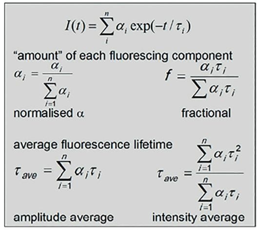
There can however, only be one exponential decay for each excited state present, and this can be represented by a sum of exponentials as show below. In this example, α (the pre-exponential factor) is indicative of the relative concentration of each t decay to the observed overall decay.
To effectively compare measurements, it is beneficial to normalize the pre-exponential factors in some fashion.
Where a comparison of each fluorescing species is needed, then the normalized α can be used. If a comparison of the contribution to steady state spectrum (overall fluorescence emission) is desirable, then the fractional or relative amplitude (in %) can be used instead. The latter of these two values is the pre-exponential factor weighted by the lifetime.

Figure 3. Equations for obtaining fluorescence lifetimes, component time constants, amplitudes, and averages
Sometimes it is equally as acceptable to represent a complex decay by showing an average lifetime, but it should be noted that this is best done by correctly modelling the complex decay itself as opposed to trying to attach a single exponential decay to it.
In many cases however, the use of amplitude average lifetime is the best option. When considering quenching experiments, nevertheless, it is better to employ the intensity average fluorescence lifetime. Published works by Lacowicz (2006) and Berezin (2010) explore the merits of these averages in much greater detail.
What is Phosphorescence?
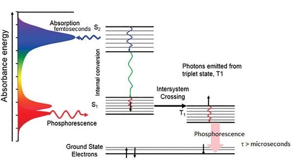
As previously mentioned, phosphorescence is the process where a photon is emitted from a forbidden triplet state rather than a singlet excited state. A fluorescence emission is often in the picosecond to nanosecond range, but phosphorescence typically lasts for microseconds, milliseconds or even longer, sometimes as long as minutes or hours.

Figure 4. Jablonski diagram for Phosphorescence emission
For phosphorescence, a pulsed source such as an LED or flash lamp is used in order to measure the spectra and decays on these longer time scales. These measurements can use a longer lived pulsed source like a xenon flash lamp, with the timing of the flashing lamp often being used to measure spectra present at various phosphorescence lifetimes.

This information has been sourced, reviewed and adapted from materials provided by HORIBA.
For more information on this source, please visit HORIBA.