A testing machine can be used to push, pull or twist a sample of the material in order to determine the mechanical properties of a material. Many materials are strain rate sensitive which means that their properties differ with test speed.

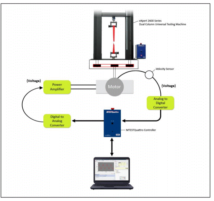
Electromechanical testing machine motor control system. Image Credit: Admet, Inc. - Materials Testing Equipment.
A valid comparison of mechanical properties between suppliers can only be attained if the same test speed is utilized by all of the suppliers. The International Standard Organization (ISO) and the American Society of Testing and Materials (ASTM) are two organizations that govern mechanical test specifications.
Each specification requires that the force be applied at a specific strain, crosshead position or stress rate. One function of the testing machine controller is to ensure that the specified test rate is accurately maintained throughout the test.
ADMET testing systems that are equipped with controllers like the MTESTQuattro controller are part of the motor control system which is responsible for regulating the motor’s speed.
The motor speed is proportional to the test rate. Control of motor speed is done by decreasing the voltage to the power amplifier if the test speed is too high, or increasing it if the test speed is too low.
One simple rule for regulating motor speed is to make an alteration in the power amplifier voltage which is proportional to the test speed error (difference between the actual and desired test speed).
Test Speed Error = Desired Test Speed – Actual Test Speed (Eq. 1)
Amplifier Voltage = Kp x Test Speed Error (Eq. 2)
Equation 2 is a proportional control algorithm. Kp is the proportional gain and is altered in order to minimize the test speed error. Using the motor control system, how effectively the test speed is controlled will be dependent on the amount of demand placed on the MTESTQuattro controller.
If the MTESTQuattro control algorithm utilized for computing the power amplifier voltage as a function of measured test speed can be updated quickly, and if the digital to analog (D/A) and analog to digital (A/D) converters as part of the controller do not need much intervention, then it is reasonable to expect minimal error between the desired and actual test speeds.
The strategy for the MTESTQuattro controller is to update the power amplifier voltage as frequently as possible, as the calculation of the power amplifier output voltage is not dependent on time (see Eq. 2). The servo update rate is defined as the time interval between each amplifier voltage computation.
The servo update rates for the examples included in this article are fixed at 1 millisecond or 1,000 times per second (1,000 Hz). See the examples below to relate the servo update rate to actual testing applications.
- Example 1: ASTM D638 Standard Test Method for Tensile Properties of Plastics specifies a constant crosshead testing speed of 2 in/min or 0.033 in/sec. With a servo update rate of 1,000 times per second, the desired crosshead movement per servo update = 0.033/1000 = 0.000033 inches/servo update.
- Example 2: Apply a 10 lbf peak to peak sinewave force amplitude at 5 Hz (cycles per second) in order to a test sample. Each cycle is to be completed every 0.2 seconds (1/5 Hz) based on the 5 Hz specification. The number of servo updates per cycle = 1000 x 0.2 = 200 servo updates per cycle. During each cycle the actuator will apply 10 lbf then remove 10 lbf from the sample for a total force traversal of 20 lbf. The average change in force per servo update is 20 lbf / 200 = 0.1 lbf/servo update.
- Example 3: Apply a 10 lbf peak to peak sinewave force amplitude at 50 Hz to a test sample. Based on the 50 Hz specification, each cycle is to be completed every 0.02 seconds (1/50 Hz). The number of servo updates per cycle = 1000 x 0.02 = 20 servo updates per cycle. The average change in force per servo update is 20 lbf / 20 = 1 lbf/servo update.
The test is carried out at a constant displacement rate of 0.000033 inches/servo update In Example 1. The motor control system is capable of following the desired test speed precisely, as the desired rate does not vary during the entire test and the control algorithm updates the amplifier voltage 1,000 times per second.
On average there is a 0.1 lbf and 1 lbf change in force per servo update in Examples 2 and 3, respectively. Yet, the motor during the sinewave profile is accelerating and decelerating continuously, creating a varying test speed error.
Accelerations get larger and there are fewer servo updates each cycle as the cycling frequency increases. So, the servo update errors will grow with increasing frequency which will demand more from the controller in order to achieve accurate control.

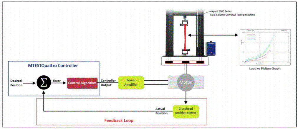
Block diagram of a test being performed under crosshead position rate control. Image Credit: Admet, Inc. - Materials Testing Equipment.
At each servo update, using closed loop control, the MTESTQuattro controller subtracts the actual crosshead position from the desired crosshead position in order to determine the crosshead position error.
- The power amplifier voltage will be zero if the error for that servo update is zero.
- Corrective action will happen if there is an error. The motor will be told to speed up if the actual position lags the desired position (positive error) or told to slow down if the error is negative. As the test progresses, the force increases but then the material begins to yield (a process disturbance). Suddenly there is less resistance to stretching the test specimen and the actual position overtakes the desired position. So that the motor slows down, the controller will decrease the power amplifier voltage. Soon after, the material might start to strain harden, causing more resistance to movement. The actual position falls behind and the controller then increases the power amplifier voltage to speed the motor up.
The testing machine would have no knowledge of it’s actual crosshead position without a feedback loop. Once a disturbance like an increasing load, yield, or rupture, is encountered, the error between the actual and desired crosshead position would vary along with the test speed.

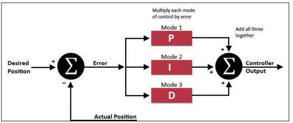
Block diagram of a PID controller. Image Credit: Admet, Inc. - Materials Testing Equipment.
The PID controller works the following way. Each servo update, the actual crosshead position is subtracted from the desired crosshead position to acquire a position error. Depending on which modes are turned on, the error is passed into one, two or all three of the P, I and D modes.
Then the outputs from each mode are combined and the resulting sum is the controller output or power amplifier voltage which sets the speed of the motor for that servo update. One, two or all three of the modes may be turned on. The most common is PI control but the possible combinations are listed below.
- Proportional Control Only, P
- Proportional plus Integral Control, PI
- Proportional plus Integral plus Derivative, PID
- Proportional plus Derivative, PD
Integral control action adds the errors at subsequent servo updates together continuously, creating a ramp like change in the power amplifier voltage. Over time, this action will drive the servo update error to zero and also overcome the changing motor resistance which is a result of varying loads during a test.
Generally, one set of crosshead position PID control gains on a static testing machine will generate acceptable crosshead position control over almost the complete speed range of the machine.
A second set of crosshead position PID control gains with larger proportional gain (Kp) and integral control gain (Ki) values may be needed for extremely slow speeds. A different set of PID control gains may be needed for cyclic waveforms differing in amplitude and frequency for fatigue testing applications, thus, requiring more frequent gain tuning.
When tuning force control loops there are several key points to consider. The stiffness of the test specimen, or how much it stretches under load relative to the stiffness of the testing machine load frame and motor control system is important.
Good control over the entire force range is achievable if the test specimen is very compliant (stretches much more) relative to the testing machine. Instability at higher forces may be experienced if the stiffness of the test specimen is equal or greater than the stiffness of the testing machine.
Make the control loop more sluggish by decreasing the proportional and integral gains in order to eliminate the instabilities at higher loads. The end result of decreasing the gains is a stable control loop at higher loads but larger control errors at lower loads.
This information has been sourced, reviewed and adapted from materials provided by Admet, Inc. - Materials Testing Equipment.
For more information on this source, please visit Admet, Inc. - Materials Testing Equipment.