Key Issues
- Highly corrosive, reactive and toxic reaction mixture
- Composition needed every 5 minutes
- Detection limits for reactants and products better than 1%
Introduction
Phosphorus trichloride (PCl3) is an essential raw material in the production of oxyphosphorus compounds for commercial use. These commercial uses are highly varied and can include oil and polymer additives, phosphate esters, pest control compounds, special lubricants and fire-resistant materials. The trichloride is produced via direct chlorination of elemental white phosphorus (P4).
This process is exothermic, taking place as a continuous reaction. Phosphorus is added to a boiling mixture of phosphorus and trichloride, while a constant stream of chlorine is added to the reactor.
Effective control of the phosphorus-to-chlorine ratio is essential if product yield is to be maximized. Proper control also ensures that an appropriate amount of heat is generated, while maintaining the stoichiometry for the trichloride’s production. Enough heat will be generated by the reaction itself to distill the product as it is formed.
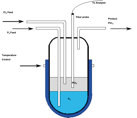
Feed and heating rates are also important, as proper management of these can help minimize the formation of the undesirable by-product phosphorous pentachloride (PCl5). An example reactor configuration for PCl3 production is displayed in Figure 1.

Figure 1. Reactor for PCl3 production. Image Credit: Kaiser Optical Systems, Inc.
Reaction Summary
| P4 + 6Cl2 → 4PCl3 + Heat |
Product |
| PCl3 + Cl2 → PCl5 + Heat |
Byproduct |
| P4 + 6PCl5 → 10PCl3 + Heat |
Uncontrolled heating |
Contaminants will build up over time, largely introduced via the phosphorus feed. Because of this, the reactor must be periodically shut down to allow for cleaning, but, before this can take place, the system must be purged of the pyrophoric phosphorus.
Cleaning is accomplished through the addition of just enough chlorine to react with the phosphorus (simultaneously ensuring that not too much is added) in order to reduce any by-product formation.
Chlorine flow should be terminated at the point where all of the phosphorus has been consumed. To maintain the essential balance in this reaction - during production and throughout the shutdown process - the reaction must be monitored with a tool that is sensitive to changes in composition and able to provide relatively fast feedback.
Experiment
The reaction’s basic ingredients are highly corrosive, chemically reactive, and challenging to analyze, even when working under normal conditions. Standard laboratory methods for this analysis are based on chromatography or wet chemistry – which is a titration with elemental bromine in a halogenated solvent.
These methods provide a partial picture depending on the condition of the reaction, only providing information on the free phosphorus (pyrophoric, P4) content. These methods are also time consuming and labor intensive, with neither method providing measurement of the phosphorus chlorides, PCl5 and PCl3.
The reaction intermediates, elemental chlorine, and reaction products are all corrosive, toxic, reactive materials. Also, a large number of these materials will react easily with moisture to form hydrochloric acid.
This, of course, places particular demands on the nature of any materials coming into contact with the reaction mixture. In order to minimize these risks, measurement should ideally be made within the reactor itself, removing any need to transfer the material.
Because of this issue of chemical reactivity, it can be especially challenging to select the right material for any optical probes, including any materials used in the fabrication of the probe, and any window materials.
All of these materials, including the phosphorus, possess characteristic Raman signatures with unique bands that can be employed to effectively monitor each component. Infrared methods are not viable here, partly because of their inability to measure elemental phosphorus, and partly because of sampling challenges, such as the lack of a remote fiber optic interface.

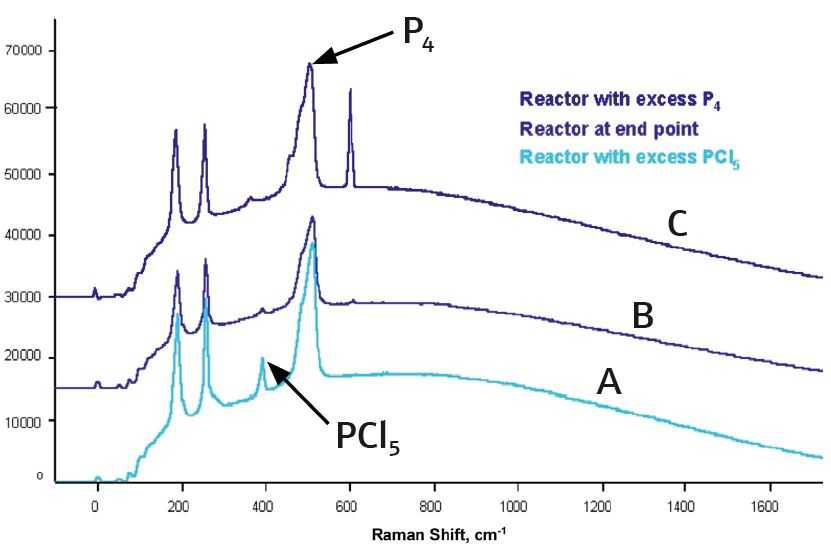
Figure 2. Raman spectra of PCl3 reaction mixture (B) and PCl3 spiked with P4 (C) and PCl5 (A). Image Credit: Kaiser Optical Systems, Inc.
Results and Discussion
The example here features data that was acquired via a Kaiser Raman analyzer system fitted with a 785 nm diode laser. Figure 2 displays spectra from reactor-grade (‘black’) phosphorus trichloride, spiked with PCl5 (A) and phosphorus (C).
The 606 cm–1 band is utilized in monitoring the presence of free phosphorus, while a band at 393 cm–1 is used for the PCl5. A fiber optic insertion probe which features a 9-around-1 bundle was employed in this instance; 400 μm inner fiber for excitation plus 200 μm outer fibers for collection.
There was some interference from the Raman silica background from the fibers, but this did not pose a problem in the accurate measurement of the phosphorus or phosphorus chlorides.
Additionally, the silica Raman signature is reproducible enough to allow its subtraction from the measured spectra of the reaction mixture. Good quality, measurable spectra, with sufficient levels of sensitivity can be obtained within a 30 second timeframe.
Conclusions
Raman spectroscopy provides the only feasible instrumental method for on-line monitoring of continuous reactions between phosphorus and chlorine in phosphorus trichloride formation.
No other optical spectroscopy technique can provide information on the components of interest – P4, PCl3 and PCl5 – while ensuring ease of sampling in this non-ideal, corrosive and hazardous environment.
The technique responds in a suitably short timeframe, providing effective feedback for the control of the process, while being able to indicate the progress of the reaction. It also reports the concentration of each of the components, with a sensitivity of <1% by weight.1
* Current model is Raman Rxn2™ analyzer
References
- Gervasio, G.J. and Pelletier, M.J., “On-line Raman Analysis of PCl3 Reactor Material,” Journal of Process Analytical Chemistry, Vol. III, No. 1&2, Fall 1997.

This information has been sourced, reviewed and adapted from materials provided by Kaiser Optical Systems, Inc..
For more information on this source, please visit Kaiser Optical Systems, Inc..