Hydraulic-magnetic and thermal circuit breakers are both utilized for safeguarding against electrical faults.
Nevertheless, for applications where harsh environments and wide ranges of ambient temperature are possible, magnetic hydraulic circuit breakers deliver advantages in circuit protection that thermal circuit breakers cannot match.
Core Design Differences
Thermal Circuit Breakers
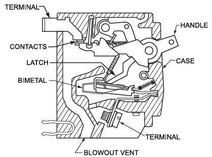
During normal operation, thermal circuit breakers utilize a thermal sensing element (such as bimetal), which deflects when the temperature reaches a predetermined calibration level, causing the circuit to open. The principal cause of temperature rise in the sensing element is the load current 12 R heating.
The thermal element integrates the effects of heating or cooling from external sources. The thermal element's size, configuration, physical shape, and electrical resistivity determine the circuit breaker's current capacity.
In situations where the current rating is below five amperes, a heater coil is placed adjacent to the thermal element, which is electrically in series with it, to boost the self-heating of the thermal trip element.
The most prevalent thermal element used is a "sandwich" of two or three different metals, with the low expansion side made of invar (a nickel steel alloy), the center of copper for low resistivity or nickel for high resistivity, and varying metals used in the high expansion side..

Figure 1. Diagram of a standard thermal circuit breaker. Image Credit: Sensata Technologies, Inc.
Hydraulic Magnetic Circuit Breakers
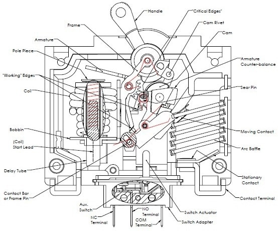
Hydraulic magnetic circuit breakers operate on a different principle than thermal circuit breakers. The magnetic time-delay circuit breaker functions on the solenoid principle, where a movable core, held by a spring in a tube, and damped with a fluid, can be displaced by the magnetic field of a series coil.
As long as the current remains at or below 100 percent of the unit's rated current, the mechanism will not trip, and the contacts will remain closed.
If the current is increased to a point between 100 percent and 125 percent of the rated current of the unit, the magnetic flux generated in the coil is sufficient to move the delay core against the spring to a position where it can rest against the pole piece.
The movement of this core increases the flux in the magnetic circuit, leading to the rotation of the armature from its normal position, which trips a pin, unlatching the collapsible link of the mechanism, and opening the contacts.
The delay tube is filled with a silicone fluid that controls the speed of the delay core's movement within the delay tube assembly, resulting in different delay curves by using fluids of varying viscosities.
In situations where high current surges occur in an electrical circuit, the magnitude of the flux produced in the magnetic circuit must be sufficient to trip the unit without the delay core changing position.
Protector delay curves that provide instant trips at surges of 600 percent or more should be utilized for the protection of UL appliances, such as those previously listed.
Focusing on the Impact of Ambient Temperature
Thermal circuit breakers rely on temperature rise in the sensing element for actuation and are consequently, by nature, influenced by ambient temperature.
While temperature (ambient) compensated circuit breakers – in which a thermal responsive element is introduced to compensate for changes in external temperatures – can be deployed, that does not change the underlying issue.
Choosing the appropriate thermal breaker is a complex undertaking that extends beyond merely matching the breaker rating with the wire rating. Ambient operating temperature, allowable voltage drop, and provided heat sinking must also be considered.
The challenge becomes even more difficult when the most critical factor, ambient temperature, is unknown.
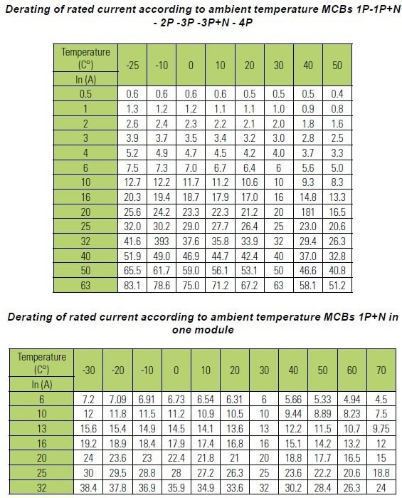
Equipment manufacturers distribute products worldwide from numerous manufacturing locations and are unaware of the environment in which their equipment will be used. Consequently, a 10 A-rated circuit breaker may trip at 7 A in high-temperature environments or as late as 13 A in colder conditions.

Figure 2. Diagram of a Magnetic Hydraulic circuit breaker. Image Credit: Sensata Technologies, Inc.
Thermal circuit breakers require de-rating based on the ambient temperature. In hot environments, the current rating is often oversized to avoid nuisance tripping, which poses a risk from an electrical protection perspective.
In colder environments, the circuit breaker may have a slower trip time and, therefore, can be underrated when it comes to addressing this issue, but this approach also compromises the primary purpose of electrical protection.
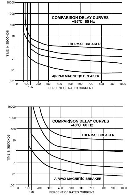
However, hydraulic magnetic circuit breakers do not face these difficulties and maintain consistent ratings, performing the range of -40 °C to +85 °C.

Figure 3. Image Credit: Sensata Technologies, Inc.

Figure 4. Image Credit: Sensata Technologies, Inc.
The hydraulic magnetic circuit breaker offers several options within its design, such as adjusting the coil windings to achieve a precise current rating.
Additional components can be incorporated to prevent nuisance tripping from high inrush currents, such as a steel shunt plate fixed to the top of the coil to shunt the effects of high inrush current or an inertial wheel attached to the armature to physically dampen the armature movement.
These options can be particularly useful in preventing nuisance tripping in circuits with high start-up inrush currents.
These components can include an integrated auxiliary switch, relay trip, and voltage coils, which can be remotely tripped if necessary, while thermal breakers require an additional half-pole module.
Each device type has its place. But for equipment that can be shipped globally, having a temperature-stable solution is critical – which is why hydraulic magnetic circuit breakers are the most effective power control component in telecommunications, data and servers, transportation and rail, defense, marine, power generation, and other areas of industry.

This information has been sourced, reviewed and adapted from materials provided by Sensata Technologies, Inc.
For more information on this source, please visit Sensata Technologies, Inc.