When using particle counters, many operators are unaware that during conventional manifold sampling, the monitor can undercount the ambient particle concentration. The manifold pump creates an additional vacuum resulting in a considerably reduced particle concentration in the air sampled compared to ambient cleanroom air.
This lower-than-expected particle density causes a 7–17% undercounting of particle concentrations unless an appropriate adjustment in the system is made. Traditionally, various compensation methods are used in the different particle counters available to compensate for this undercounting.
Until now, none of these compensation techniques have brought about truly accurate numbers; some have even resulted in increased errors, such as particle mis-sizing, which in turn led to 40% underreporting in the first channel.
Particle Measuring Systems has recently developed a system where these counting errors are eliminated automatically. When used in combination with the Aerosol Manifold II, the Lasair® III counter's proprietary system for pressure monitoring and flow control makes it possible to normalize the raw counts and calculate accurate cleanroom particle concentrations with good accuracy for the first time.
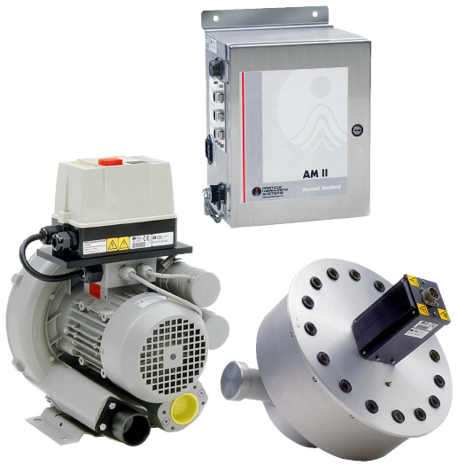
Figure 1. AM II 16 Aerosol Manifold System. Image Credit: Particle Measuring Systems
Introduction
The Lasair® III Aerosol Particle Counter is the next generation of aerosol particle counters from Particle Measuring Systems. The Aerosol Manifold II was developed to work with the Lasair III under the control of Particle Measuring Systems facility monitoring software (Facility Net).
This article outlines the intrinsic measurement errors typical of manifold monitoring, then discusses the patented pressure measurement and normalization techniques that PMS uses to eliminate these issues.
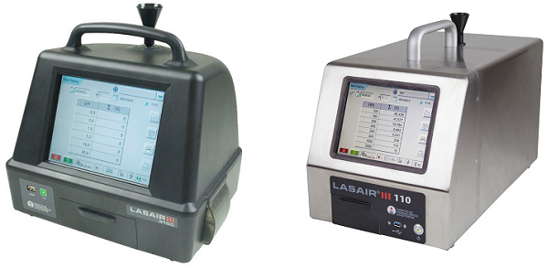
Figure 2. (Left) Lasair III 310C Aerosol Particle Counter and (right) Lasair III 110 Aerosol Particle Counter. Image Credit: Particle Measuring Systems
Particle Undercounting in Manifold Systems
In conventional manifold systems, air is pulled from as many as 32 different monitoring locations simultaneously using a powerful pump. The pump must be able to create a strong vacuum as each location can be as far as 125 feet away which is exacerbated by the cumulative length of tubing, plus the volume of air being moved.
Therefore, the particle counter must be able to sample air from the manifold at a vacuum. The counter no longer pulls in the air at room pressure; this increased vacuum (i.e., lower pressure) in the particle counter causes an error in the measurement of ambient particle concentration.
A 1.0 CFM particle counter is engineered to generate a 1.0 CFM flow at a constant velocity at the sample inlet pressure. In isolation (non-manifold), the sample inlet pressure is the same as the atmospheric pressure, so the unit maintains a 1.0 CFM flow, plus or minus its nominal tolerance (e.g., 5%).
However, when attaching a manifold, the entire system functions at a lower than ambient pressure; this is due to the vacuum required to draw air through the long lengths of manifold tubing.
As a result, a lower concentration of particles will be observed in the 1.0 CF sampled at the inlet compared to 1.0 CF of ambient air (see Figure 3). This means the particle count per cubic foot with a manifold will be proportionately lower than if sampled from the ambient air directly.
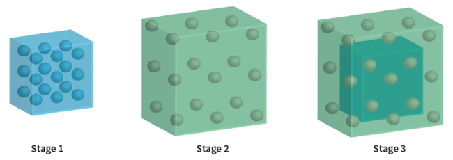
Figure 3. Impact of manifold vacuum on particle concentration. Image Credit: Particle Measuring Systems
Stage 1: 1.0 CF sample of ambient air has a defined particle concentration.
Stage 2: Once this sample enters the manifold tubing it expands as a result of the vacuum created by the manifold pump; particles are scattered over a larger volume.
Stage 3: The particle concentration is lower than in the ambient air when the counter samples its 1.0 CF of manifold air at the sample inlet pressure.
To deliver truly accurate results, the manifold system must compensate for this pressure adjustment. Therefore, it is worth reviewing the pressure measurement system to fully understand how the Lasair III compensation system works.
Pressure Measurement in the Lasair III
The Lasair III particle counter uses a patented pressure measurement system to circumvent the undercounting problems usually associated with using a manifold. At the core of the system are three separate pressure transducers:
- The pressure inside the sample inlet is monitored by the first pressure transducer. This sensor allows the Lasair III to measure and correct for the vacuum generated by the manifold pump.
- A differential pressure sensor gauges the difference between the pressures before and after the sample cell. The Lasair III leverages this information to control the flow rate and velocity through the sample chamber.
- The ambient atmospheric pressure is measured using a third-pressure transducer. Figure 5 shows the pressure sensor system Lasair III uses to identify and compensate for flow anomalies.
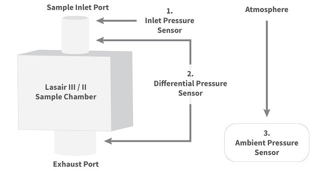
Figure 4. Lasair III/II Pressure Sensor System. Image Credit: Particle Measuring Systems
Concentration Correction Factor with the Lasair III
Using the data from the sample inlet and the differential pressure sensors allows the Lasair III to servo-control the airflow. This information is used to regulate the Lasair III blower/pump to produce a 1.0 CFM flow rate at a constant velocity at the sample inlet pressure.
In conventional sampling, this sample inlet pressure is roughly the same pressure as in the cleanroom. However, when a manifold is employed, the air at the inlet is at a partial vacuum in relation to the cleanroom air. Thus, the 1.0 CF sampled exhibits lower particle concentrations than 1.0 CF of ambient cleanroom air.
To adjust for this phenomenon, the Lasair III counter calculates the equivalent ambient volume sampled (instead of the nominal 1.0 CF). This is achieved by multiplying the measured sample volume times the ratio of the density of the air at the inlet to the density of ambient cleanroom air:
Equivalent Ambient Sample Volume (CF) = MEASURED VOLUME x INLET DENSITY / AMBIENT DENSITY (1)
which can be simplified to:
Equivalent Ambient Volume (CF) = MEASURED VOLUME x INLET PRESSURE / AMBIENT PRESSURE (1a).
Example:
Calculating Equivalent Ambient Volume
Manifolds pulls in around 25 to 50 inches of H2O (or 6.2 to 12.4 kPa) of vacuum.
The approximate atmosphere at sea level is 101.3 kPa.
- What is the equivalent ambient sample volume at 25 inches H2O of vacuum (at sea level)?
1.0 CF x (101.3 kPa – 6.2 kPa) / 101.3 kPa = 0.939 CF.
- What is the equivalent ambient sample volume at 50 inches of H2O of vacuum (at sea level)?
1.0 CF x (101.3 kPa – 12.4 kPa) / 101.3 kPa = 0.878 CF.
Normalizing Counts in Software
With the equivalent ambient sample volume calculated, the raw particle counts can then be properly normalized:
Normalized particle count (N/CF) = OBSERVED PARTICLE COUNT / EQUIVALENT AMBIENT SAMPLE VOLUME (2),
which equates to:
Normalized particle count (N/CF) = OBSERVED PARTICLE COUNT x AMBIENT PRESSURE / INLET PRESSURE (2b).
The Lasair III manifold system transmits both raw counts and equivalent ambient sample volumes to Facility Net, which then runs the normalization calculations. (For instance, for a sample volume equivalent to 0.93, the normalization factor would be 1.0/0.93 = 1.075.) If needed, the raw counts can still be accessed.
Correction/Normalization Table
Table 1 illustrates the equivalent ambient sample volumes (compared with the nominal 1.0 CF sample volume) across a broad range of manifold operating conditions. Notice that the equivalent sample volume may require correction for both altitude and the manifold vacuum.
Table 1. Equivalent Ambient Sample Volume (CF) in Manifold Systems. Source: Particle Measuring Systems
| Altitude (ft) |
Manifold Vacuum (inches of H2O) |
| 30 |
35 |
40 |
45 |
50 |
55 |
| 0 |
0.93 |
0.91 |
0.90 |
0.89 |
0.88 |
0.86 |
| 1000 |
0.92 |
0.91 |
0.90 |
0.88 |
0.87 |
0.86 |
| 2000 |
0.92 |
0.91 |
0.89 |
0.88 |
0.87 |
0.85 |
| 3000 |
0.92 |
0.90 |
0.89 |
0.87 |
0.86 |
0.85 |
| 4000 |
0.91 |
0.90 |
0.88 |
0.87 |
0.85 |
0.84 |
| 5000 |
0.91 |
0.89 |
0.88 |
0.86 |
0.85 |
0.83 |
As displayed in Table 1, when a manifold system is used, the equivalent ambient volume sampled will only be 83–93% of the 1.0 CF sampled by the particle counter. Particle concentrations will undercount between 7–17% in systems that fail to properly compensate.
Shortcomings of Alternative Compensation Techniques
Over the years, particle counter users have relied on a variety of techniques to compensate for this undercounting phenomenon. The most common has been increasing the pump speed upon installation so the equivalent ambient volume is closer to the nominal 1.0 CFM.
As an alternative, several manufacturers have tested the use of a mass flow controller to servo-control the pump. Such controllers boost the volume flow automatically to ensure that the target mass is sampled by the particle counter. Thus, the same mass is sampled as in 1.0 CFM of ambient air. However, both of these techniques necessitate increasing the velocity through the sample chamber.
This leads to two problems: First, a velocity increase leads to a calibration loss in the traditional particle counter, to the point that it no longer meets JIS specifications. Second, increasing the sample velocity also leads to a new kind of problem: particle-sizing errors.
Particle size is determined using a counter by evaluating the shape of the pulse a particle produces as it passes through the laser beam: the shape recognition algorithms used to accomplish this are set during calibration. However, if the same particle passes through the beam at a faster rate, the pulse emitted is smaller; this results in a misclassification of some percentage of particles leading them to be identified as belonging to a smaller size channel. In the smallest size channel, some particles will not be counted whatsoever.
Thus, counting efficiency is compromised when increasing the sample velocity. Moreover, where previously it was possible to calculate the degree of undercounting, now the size of the error becomes extremely complicated to anticipate.
Figure 5 shows the particle-sizing errors brought about by increasing the sample velocity in a manifold system. This graph exhibits three separate tests run on a Lasair III connected with the Aerosol Manifold II via a 125-foot sample line.
The first bar shows counting losses (in 0.3 µm particles at 50 inches of H2O pressure) when an increase in the sample velocity was carried out to achieve an equivalent ambient flow rate of 1.0 CFM. Note that the counts plummeted to under 60% of those seen by the reference unit. While these data reflect the first channel, the higher channels were also affected.
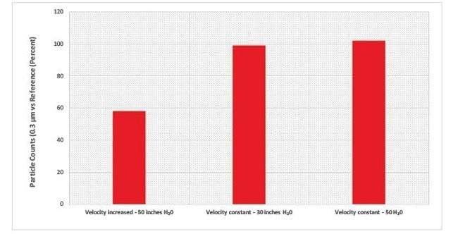
Figure 5. Particle Sizing Errors Due to Increased Sample Velocity. Image Credit: Particle Measuring Systems
The subsequent bars displayed in Figure 5 reveal how normal sample velocity was maintained so that the unit pulled in its normal 1.0 CFM at a constant velocity at the sample inlet pressure. For these examples, the normal counting efficiency was maintained; counts were close to 100% of those seen by the reference unit.
The Lasair III system prevents under-sizing errors, in addition to preventing original undercounting errors. It circumvents under-sizing errors by ensuring the same sample velocity is maintained throughout. It then uses Facility Net to normalize the data correctly to eliminate any undercounting errors.
Conclusions
Due to its powerful vacuum effect, the manifold pump can cause a reduction in the particle concentration of the sample when compared to the particle concentration of ambient cleanroom air. Unless the system makes the right adjustment to compensate for this phenomenon, this lower concentration leads to under-reporting, typically under-counting between 7–17%.
Previously, manifold sampling systems had either simply ignored this error or applied some kind of compensation system. Until now, all of these compensation techniques failed to produce truly accurate counts. This is partly due to the fact most have been based upon increasing the sample velocity; this, in turn, has led to particle under-sizing errors, which also caused under-reporting in the first channel by as much as 40%.
The Lasair III is the only manifold system that makes corrections for both issues. Leveraging the data from the patented pressure-sensor system, the Lasair III calculates the pressure-corrected, equivalent ambient sample volumes, and then transmits the normalization factors required to generate accurate measurements to Facility Net.

This information has been sourced, reviewed and adapted from materials provided by Particle Measuring Systems.
For more information on this source, please visit Particle Measuring Systems.