Power plants today frequently face challenges in providing reliable power to customers. To achieve the “Three Rs” of power system reliability—resource adequacy (covering people, equipment, and facilities), system resiliency (the capacity to recover from disruptions), and operational reliability (ensuring assets operate without unplanned downtime)—power suppliers must manage numerous complexities.
Operational reliability focuses on predicting and managing critical asset downtime to prevent disruptions in power supply. For years, condition-based maintenance (CBM) tools, such as oil analysis, have been essential in enhancing the reliability of lubricated assets within power generation facilities.
Recent advancements, particularly in onsite oil analysis technologies, are transforming how operators utilize the data from oil analysis. This article will evaluate some case studies involving oil analysis and explore how new technologies can resolve issues more quickly and cost-effectively than previously reported.
This case study illustrates how a large US power plant avoided a costly shutdown through the use of established fault-tolerant and fault-recovery techniques, including oil analysis and vibration analysis.
By following the onsite CBM procedure outlined in Figure 1, technicians were able to continue normal operations, address a false alarm, and implement the necessary corrective actions.
Before proceeding with expensive maintenance based on abnormal alarms, onsite technicians retest and resample to ensure accurate recommendations. This case study also highlights opportunities where new technologies could provide clearer insights into the core issue: Babbitt-type bearing wear debris.
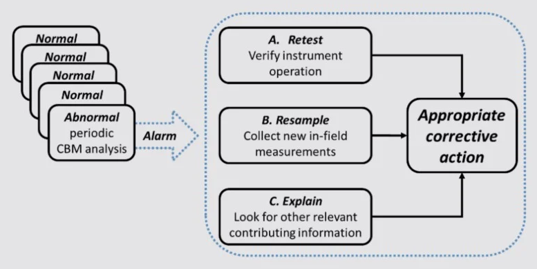
Figure 1. Fault tolerant and fault recoverable onsite condition-based maintenance (CBM) procedures. Image Credit: AMETEK Spectro Scientific
Case History
This case history begins with the Unit 1 steam turbine/generator. The turbine oil tank, which holds 10,000 gallons, raises, lubricates, and cools the rotor of an 800 MW steam turbine generator. The lubricant runs through twelve Babbitt-type bearings. Ten of the twelve bearings weigh around one ton each.
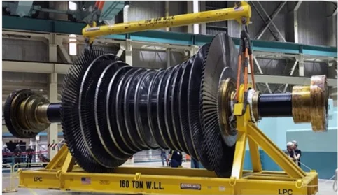
Figure 2. One compression stage from an 800 MW steam turbine. Image Credit: AMETEK Spectro Scientific
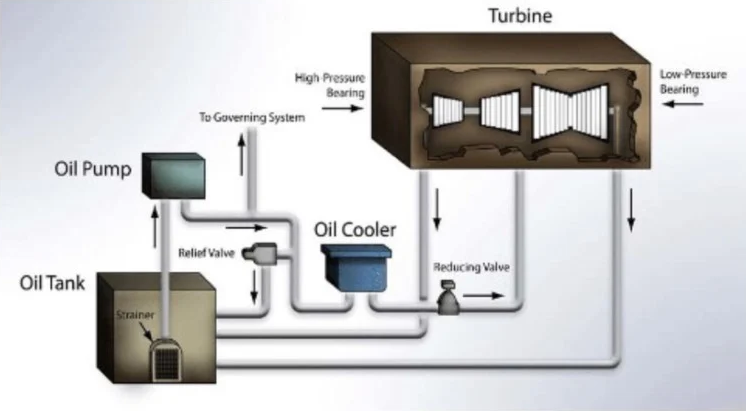
Figure 3. Simplified diagram of oil flowing into and out of turbine Bab bitt-type bearings. Image Credit: AMETEK Spectro Scientific
Power plant CBM technicians collected and tested oil samples from critical equipment monthly using the onsite MiniLab analyzer to assess oil chemistry, contamination levels, and large ferrous wear debris.
On one occasion, a routine analysis of Unit 1 turbine oil revealed alarming levels of wear and contamination due to large ferrous particles and a high particle count. This unexpected result raised significant concerns about potential bearing damage and contamination of the large oil compartment.
Several critical questions emerged: Was there a genuine issue? Could the sampling procedure have introduced contamination? Was the onsite analyzer functioning correctly? Did the problem involve turbine bearings or the lubrication system?
Following their standard procedure, outlined in Figure 1, CBM vibration and oil analysts were prepared to address such alarming findings. They promptly retested and reanalyzed the measurements to ensure the accuracy of their instruments.
New samples were collected and tested onsite, and potential causes of the abnormal findings were investigated. Based on the initial and retested results, along with possible explanations, appropriate corrective actions were recommended.
The issue began when a routine oil sample from Unit 1's steam turbine/generator triggered high wear and contamination alarms. Historically, the trend for this sample point showed normal wear, contamination, and chemistry.
However, this sample displayed large ferrous particles and high particle counts but normal viscosity and chemistry. Following protocol, the onsite MiniLab operator immediately retested the sample, obtaining the same alarming results. Confirming that the MiniLab instrument and procedures were accurate, the lubrication technician collected a second sample from the Unit 1 turbine oil tank.
The second sample, tested with the same procedures and instruments, did not show alarming results; it was free of large ferrous particles and had a normal particle count consistent with historical trends.
The discrepancy between the first alarming sample and the second normal sample raised a critical question: Why did the initial sample show high levels of ferrous wear particles while the second was clean and fit for use? Given that any abnormality reported by a CBM tool required immediate action, including possibly taking the unit offline, it was essential to determine the root cause of the first sample's results.
Root Cause Investigation
CBM technicians investigated the area around the Unit 1 turbine oil tank and discovered that maintenance work had been carried out in the vicinity over the past 30 days. They found that grinding operations on the fifth floor above the sampling point had likely resulted in metallic dust and debris contaminating the sample container when the first sample was collected with the lid off.
Additionally, turbine operators had reported no recent issues for the Unit 1 steam turbine/generator, and vibration surveillance and protection systems detected no issues. Therefore, the abnormal results from the initial test were attributed to the contamination of the sample container, which led to false positive findings.
The resampled and retested oil confirmed that the lubrication system was in good condition for continued use, and further inspections supported the decision to keep Unit 1 operational.
As a result, the potential turbine shutdown was avoided. A Corrective Action Report (CAR) was issued to enhance standard oil sampling procedures, ensuring improved accuracy and reliability in future analyses.
Cost Avoidance
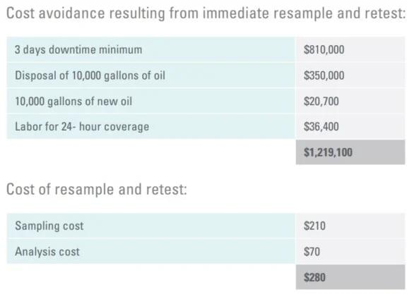
Without on-site oil analysis tools, obtaining test results would have taken an additional three days, during which time the unit would have been taken offline while the investigation was underway.
A further three days would be required to receive results from a second sample, resulting in costly downtime at $270,000 per day, not including expenses for new oil, disposal of the used oil, and labor costs.
Had the first sample's results been accurate, contaminated oil could have circulated through the bearings for three or more days, likely causing additional damage and extending the downtime.
Source: AMETEK Spectro Scientific
Turbomachinery with Babbitt-Type Bearings
In this situation, false positive wear and contamination alarms from the initial oil sample were effectively tested and verified. The true negative findings reported by the second sample, which was collected and immediately analyzed, helped prevent any unnecessary maintenance actions.
Both tests utilized ferrous density and particle counting measurements. Ferrous density measurements are particularly useful for detecting abrasion, adhesion, and fatigue in roller bearings and iron alloy gears.
However, it is crucial to note that ferrous density measurements are less effective for monitoring Babbitt-type bearings, which are primarily composed of copper, lead, tin, and antimony.
Wear debris from iron alloy journals, roller bearings, and gears can be detected using ferromagnetic ferrous density measurement devices. For more accurate results with the twelve Babbitt-type bearings in this steam turbine, it is recommended to use (1) active zone sampling from the return line and (2) multi-element large wear debris analysis.
The introduction of the new filtergram particle quantifier, which combines X-ray fluorescence (FPQ XRF) for pore blockage particle counting and energy dispersive X-ray fluorescence for multi-elemental analysis, enhances onsite oil analysis capabilities.
The FieldLab 58 onsite oil analyzer, as depicted in Figure 4, offers detailed insights into machine wear, system contamination, and lubricant condition. This analyzer provides actionable data, enabling onsite personnel to plan for necessary repairs or design changes.
The FieldLab 58 utilizes MiniVisc and FluidScan tests to assess lubricant viscosity, chemistry, and contamination. Additionally, it incorporates the FPQ filtergram process for pore blockage particle counting, X-ray fluorescence wear debris analysis, and specimen examination for further analysis as required.
The FieldLab 58 XRF is particularly suited for turbines, generators, feed water pumps, Babbitt bearing applications, sleeve bearings, and worm drive gears. The XRF module non-destructively analyzes wear debris of common elements—such as Fe, Cu, Pb, Sn, Si, Al, Cr, Ti, Ni, Mg, Mn, Ag, V, W, Zn, and Co—across a size range from 4 microns to millimeters.
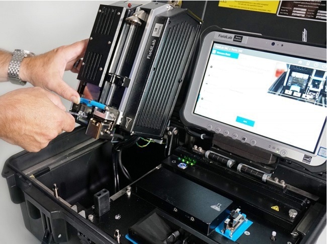
Figure 4. FieldLab 58 portable fluid analysis system reports kinematic viscosity, infrared chemistry and contamination, pore blockage particle count, and X-ray fluorescence multi-element large particle wear debris analysis. Image Credit: AMETEK Spectro Scientific

This information has been sourced, reviewed and adapted from materials provided by AMETEK Spectro Scientific.
For more information on this source, please visit AMETEK Spectro Scientific.