Comprehensive oil analysis requires sampling, testing, and analyzing in-service industrial lubricants to assess machinery wear, lubrication system pollution, and lubricant chemistry.
This article purposely concentrates on the analysis of large wear particles since the resulting analysis information allows users to schedule planned maintenance rather than surprise, unexpected repairs.
Large wear particle analysis is a necessary step for accurate industrial oil analysis. Typical industrial wear mechanisms, such as fatigue, adhesion, and abrasion, produce massive wear particles.
These telltale metal shards include vital information on the wear process, wearing component identity, the quantity and severity of damage, and failure development.
Wear debris analysis is divided into two categories: large (>5 µm) and small (<5 µm). Small wear debris is often made up of metal oxide, whereas large wear debris usually contains base metal as well as metallic oxide.
In addition, optical emission spectrometers (OES) are able to accurately identify minuscule wear debris. However, these precise and accurate multi-element OES analyzers have measurement limits due to their tiny size, which excludes the majority of abrasive, sticky, and fatigue wear debris.
This article presents methods for measuring and analyzing large wear particles, as well as best practices for evaluating and modifying meaningful alert thresholds for these measurement parameters.
Avoid Unplanned Repairs and Downtime
Unplanned repairs and downtime are typically over ten times more expensive than scheduled repairs. For example, a $1,800 planned roll-bearing repair equals $98,600 in unanticipated repair expenses.
Planning takes time, and it takes a lot of it. Comprehensive oil analysis, including large wear particle analysis, is one technique to save time when planning and scheduling tasks.
Onsite study of wear, pollution, and chemistry provides important findings and recommendations based on:
- Identified mechanisms of wear
- Trends of wear rates
- Determinations of root causes and severities
- Logical recommended actions with sufficient time for planned repairs
Common Mechanisms for Component Failures
Table 1. Common failure Mechanisms. Source: AMETEK Spectro Scientific
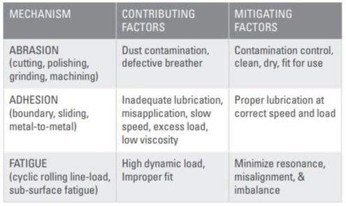
Abrasion, adhesion, and fatigue are three of the most typical failure mechanisms for industrial machinery components as they wear from incipient to catastrophic.
Table 1 summarizes these pathways, including contributing and mitigating aspects for each.
Figure 1 displays the mechanics of the abrasion, adhesion, and fatigue mechanisms, as well as examples of significantly damaged components and massive wear particles from each mechanism.
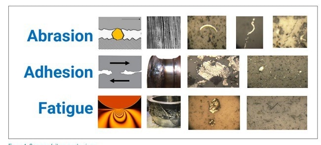
Figure 1. Common failure Mechanisms.Image Credit: AMETEK Spectro Scientific
Catastrophic failure intervals are shortened from decades to years to months due to these several contributing causes. Corrosion and/or shaft current erosion altered the shape of bearing and gear components.
Wear Particle Size Ranges
Figure 2 depicts the wear particle size ranges for different levels of wear: benign wear, severe wear, advanced wear, and catastrophic wear.
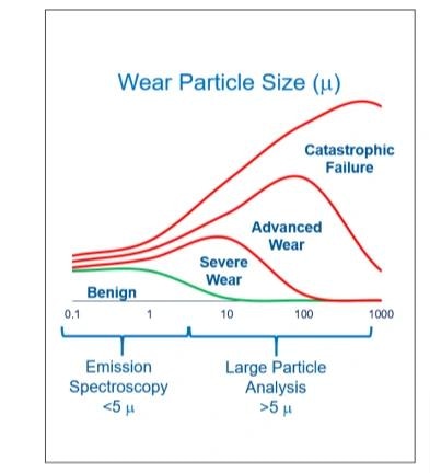
Figure 2. Wear particle size for benign, severe, advanced and catastrophic wear debris. Image Credit: AMETEK Spectro Scientific
Benign wear particles are ideal for emission spectroscopy analysis due to their size and behavior. These particles, typically ranging from submicron to 5 microns, are dispersed and suspended by Brownian motion. They result from mild rubbing rather than severe sliding and consist of surface oxides rather than base metals. Because of their small size, benign wear particles are difficult to separate from the in-service lubricant.
In the context of in-service diesel engine oils, thresholds for benign wear particles are often high in parts per million (PPM) of Fe, Cu, and Pb due to corrosive and rubbing interactions. In contrast, in-service rotating industrial machinery often exhibits zero or near-zero levels of these benign wear particles.
Abnormal wear particles are too large to be effectively analyzed using optical emission spectroscopy (OES).
Abnormal wear particles, such as those from abrasion, adhesion, and fatigue, are larger and contain base metal. Microspall particles range from 10 microns to 50 microns, while laminar particles and chunks can range from 50 microns to several hundred microns. Since OES cannot detect these larger particles, alternative analysis methods are required for accurate assessment.
Large Particle Analysis Techniques
Large particle analysis methods include automatic particle detectors, large particle specimens, visual analysis, elemental analyzers, and combinations of these to evaluate aberrant wear debris from in-service oil samples.
Automatic Large Particle Detector
- Automatic particle counters use either filter pore blockage, which leads to flow or pressure decay, or light extinction and obscuration techniques. In these methods, particulates in a flowing sample of in-service lubricant pass by a single-pixel sensor. While these techniques are effective for general contamination control, they are not designed for detailed wear debris analysis.
- Automatic direct imaging particle counters with shape classification utilize light obscuration to analyze particles in a flowing sample of in-service lubricant. As the sample passes by a focal plane array sensor, the system counts, sizes, shape-classifies, and shadow-images numerous particles per frame. This advanced particle counting method is effective for controlling contamination, eliminating false positives, and identifying aspects of larger abrasive, adhesive, and fatigue wear debris. Particles sized at 4 microns and above are counted, while those 20 microns and larger are classified. Refer to Figures 3 and 4 for additional details.
- Automatic ferrous particle counters utilize ferromagnetic sensing techniques to detect, count, and size large ferrous wear debris in a flowing sample of in-service lubricant.
- Total ferrous PPM or other ferrous density index sensory techniques detect and quantify a ferromagnetic or diamagnetic or paramagnetic sensory response when a contained substance is presented to the sensory device.
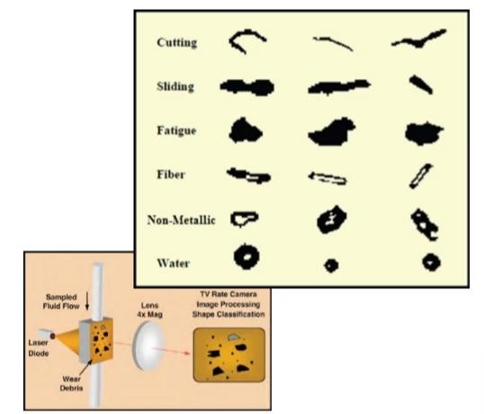
Figure 3. Automatic direct imaging particle counter with shape classification per ASTM D7596. Image Credit: AMETEK Spectro Scientific
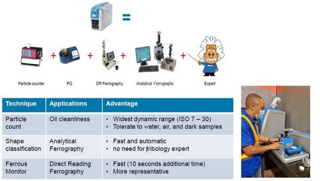
Figure 4. Automatic direct imaging with shape classification and ferrous monitor. Image Credit: AMETEK Spectro Scientific
Large Particle Extraction Specimen
- Ferrogram: A glass microscope slide separates wear and particle substances from lubricants using an inclined plane or centrifugal force to drain fluid and retain solids. Magnetic field lines of flux segregate ferrous and non-ferrous particles.
- Filter Rotrode: Vacuum filtration of in-service lubricant through a semi-porous rotrode electrode collects debris on the outer diameter surface of graphite electrodes.
- Filtergram: A filter patch separates larger particulates from in-service fluid, allowing smaller particles to pass through. Size or ferrous composition can be utilized to differentiate with sequential filters and magnetic separators. It should be noted that the filter pore blockage particle counters may create a filtergram following ASTM D8127.
- Magnetic plug or chip detector (MCD tab). Some ferromagnetic trash accumulates on a magnetic surface within an oil compartment or moving fluid system. The plug is periodically removed, and debris from it is inspected and/or transferred for further investigation and analysis.
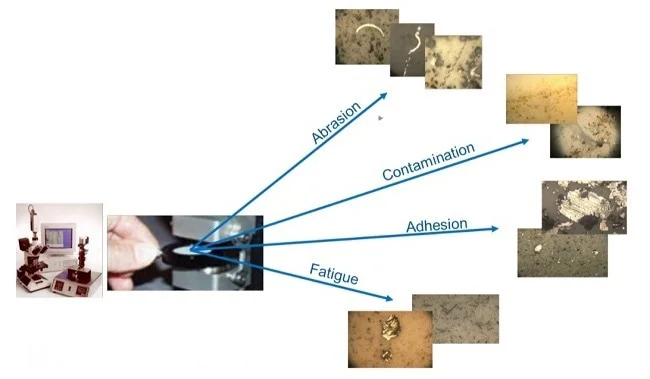
Figure 5. An automated microscope technique, such as shape classification, reduces burden on the expert. Image Credit: AMETEK Spectro Scientific
Visual Analysis
- Technicians can analyze large particle specimens with magnification and compare them to a wear particle atlas.
- Visual inspection can identify abrasion, adhesion, and fatigue mechanisms that cause large wear particles (see Figures 1 and 5).
- Magnetic analysis can assist in distinguishing between ferrous and non-ferrous materials.
Elemental Analysis
- Optical emission spectroscopy (OES): A specimen preparation, such as filter rotrode spectroscopy (FRS), is often used in conjunction with a traditional rotrode spectroscopy sample test to identify PPM large particles from fluid and tiny particulate readings.
- Scanning electron microscopy (SEM): A large particle separation specimen, such as a magnetic chip detector (MCD tab), acquires significant wear debris. These separated particles are studied using an SEM analytical technique known as energy dispersive X-ray.
- X-ray fluorescence (XRF): A filtergram, MCD tab, or other large particle separation specimen is used to do XRF elemental analysis of large wear particles, revealing PPM iron, copper, lead, silicon, and other elements.
Comprehensive Onsite Oil Analysis
Comprehensive oil analysis requires sampling, testing, and analyzing in-service industrial lubricants to assess machinery wear, lubrication system pollution, and lubricant chemistry.
Figure 6 visually depicts the overall findings for predictive component wear, proactive contamination, and proactive fluid chemistry conditions.
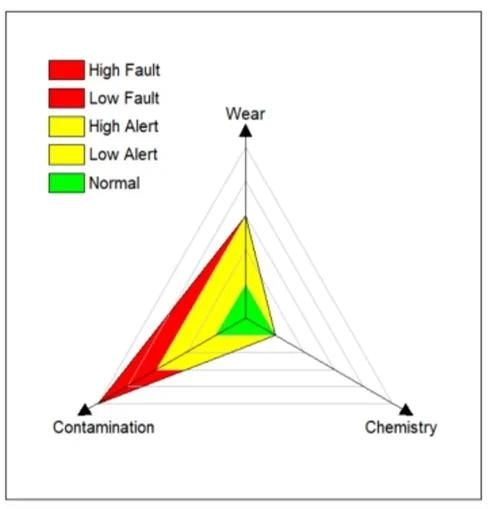
Figure 6. Trivector™ reports alarm status for wear, contamination and chemistry alarm status. Image Credit: AMETEK Spectro Scientific
Comprehensive onsite oil analysis offers various benefits to equipment owners and maintainers.
- Immediate testing and retesting for wear, contamination, and chemistry. Immediate re-testing reduces the likelihood of false positive or false negative results due to misapplication, sample, or testing errors. Before performing costly maintenance and repairs, it is routine practice to resample and retest the results with on-site oil analysis.
- Test incoming lubricants. To ensure target cleanliness standards and minimize misapplication and cross-contamination, incoming lubricants should be inspected and tested per best practices.
- Plant maintenance is responsible for owning and controlling the lubrication program, not vendors or contractors. Motivated technicians who actively participate in onsite oil analysis observe, note, interpret, and apply knowledge to enhance lubrication.
- Validate quick on-site oil sampling and testing to identify and address contamination issues.
- Onsite oil analysis is versatile for expanding projects. Begin with 25 oil compartments, then increase to 50, 100, and so on. Set goals, track progress, and exchange outcomes and case histories.
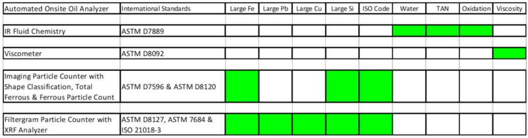
Table 2 shows that fluid chemistry, contaminants, and viscosity can be monitored using methods such as ASTM D7889 infrared analysis and the ASTMD8092 kinematic viscometer.
In addition, this table proposes the first and second-best approaches for large wear particle analysis and particulate contamination reduction.
According to ASTM D7596 and D8120, the first option for large particle analysis is to employ a direct imaging particle counter with shape classification, total ferrous, and ferrous particle count.
This option measures total ferrous PPM, classifies wear mechanisms by form, and quantifies large ferrous and non-ferrous particulate debris.
According to ASTM D8127, D7684, and ISO21018-3, the second alternative for large particle analysis is to employ a filtergram particle counter in conjunction with XRF elemental analysis. This option calculates PPM ferrous, lead, copper, and silicon.
Table 2. Combining instrumentation options to performing Comprehensive onsite oil analysis. Source: AMETEK Spectro Scientific
Oil Analysis Alarm Limits
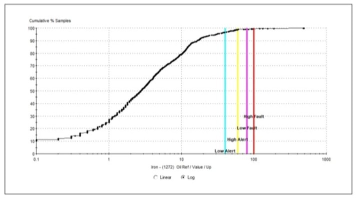
Figure 7. CDF and Alarm Limits for a Gear dataset wth 1272 Measurements from 163 points. Image Credit: AMETEK Spectro Scientific
Alarm limits are thresholds that distinguish between normal and abnormal condition values based on previous oil analysis parameter measurement experience with similar equipment working under similar conditions and employing similar test procedures.
ASTM D7720 is a good guide for determining and changing oil analysis warning limits. A statistical cumulative distribution function (CDF) can be used to determine alert limits for Gaussian normal or causal datasets, according to the ASTM Standard Guideline (D7720).
Keep in mind that significant wear debris measurement is causative, thus it must be assessed using CDF to find acceptable warning level percentile limits.
Using a single test procedure, it is simple to create a CDF and find the median, 94th percentile, 97th percentile, and 99th percentile parameter values from a dataset of similar equipment running under comparable conditions.
By following these Guidelines, the lubrication technician is alerted to detect and prepare for action on 3 % of the total set of equipment, and it is proposed that maintenance action be authorized on 1 % of the total set.
The onsite lubrication professional should comprehend the logical relationship between large wear debris measurement parameters and potential sources of alarming readings. This understanding is based on onsite equipment, onsite analysis, repair history, direct observation, and collective experience.
Figure 7 shows the CDF and alert limits for Fe PPM obtained with rotating disc spectroscopy (RDS). This dataset contains 1272 measurements from 163 gearboxes that operate under similar conditions.
Alarm limits for this equipment profile are 40 PPM low alert, 60 PPM high alert, 80 PPM low fault, and 100 PPM high fault. The CDF indicates that 4 % of measurement values exceed the alarm level, whereas less than 1% exceed the low fault.
Conclusion
This article purposely concentrates on the analysis of large wear particles because the ensuing analysis information allows knowledgeable users to plan maintenance rather than respond to unexpected, unplanned repairs.
Large wear particle analysis is a necessary step for accurate industrial oil analysis. These telltale metal shards include vital information on the wear process, wearing component identity, the quantity and severity of damage, and failure development.
Wear debris analysis is divided into two categories: large (>5 µm) and small (<5 µm). Small wear debris is often made up of metal oxide, whereas large wear debris usually contains base metal as well as metallic oxide.
This article presents methods for measuring and analyzing large wear particles, as well as best practices for evaluating and modifying meaningful alert thresholds for these measurement parameters.

This information has been sourced, reviewed and adapted from materials provided by AMETEK Spectro Scientific.
For more information on this source, please visit AMETEK Spectro Scientific.