Oil analysis is one of the most significant and dependable approaches for keeping these assets operational.
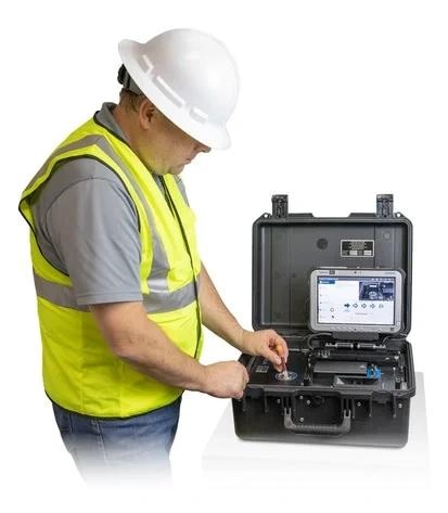
Image Credit: AMETEK Spectro Scientific
A complete oil analysis requires only 12 ml of oil and no chemicals or solvents for sample preparation or cleaning. The whole analysis, including all four tests, takes around 5 - 7 minutes, depending on oil viscosity.
When determining which approach is appropriate for your application, it is important to understand what measuring techniques are currently available and how they are employed in various sectors. This article analyzes existing analytical tools for assessing wear conditions and introduces novel methodologies developed in the FieldLab.
Existing Machine Failure Measurement Techniques
Nowadays, on-site and third-party oil analysis laboratories use a variety of machine failure measurement methodologies. These strategies benefit a wide range of industries, including manufacturing, pharmaceuticals, pulp and paper, mining, food and beverage, and alternative energy.
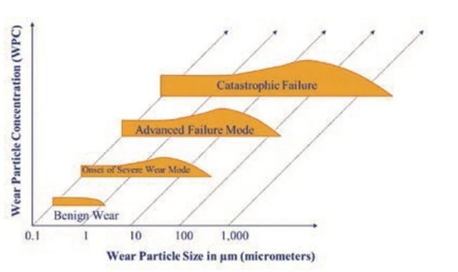
Image Credit: AMETEK Spectro Scientific
Particle Count
Particle count can help evaluate the severity of a wear condition by tracking the transition from small to large particles. Particle counting is done using one of three techniques: optical particle counting with laser light blocking, direct imaging, or pore blockage.
Oil analysis laboratories use all three of these procedures; however, laser light is the most popular. A count of particles/ml for sizes >4 microns, >6 microns, and >14 microns is provided, along with an ISO code as specified by ISO 4406.
Particle Counting Techniques
Optical Particle Counting: The most commonly used approach in laboratories is optical particle counting with laser light blocking. A laser light source travels through a sample. Because particles partially block light, less light reaches the photodetector array, causing a voltage change proportionate to the particle area.
It is vital to note that oil samples containing considerable levels of water and/or air bubbles require additional sample treatment to eliminate the bubbles. If not, the findings will be skewed, greatly increasing the ISO Code. Excess varnish in samples may potentially skew particle count readings.
Direct Imaging Particle Counters: This technique employs a pulsed laser diode and a CCD photo chip. The laser illuminates the sample while an optical lens magnifies the laser light. A camera takes photographs of the sample and stores them in memory. An ISO particle count is displayed, and the camera can also analyze the photos for size and form.
Pore Blockage Particle Counters: This technique employs a mesh screen to count oil particles. It is either a constant pressure or constant flow approach, and the particles collect on the mesh screen. The particle count data is then extrapolated to yield an ISO code.
Atomic Emission Spectroscopy
Elemental identification of wear particles has historically been accomplished by atomic emission spectroscopy utilizing either Rotating Disc Electrode (RDE) or Inductively Coupled Plasma (ICP) technologies.
Both of these methods are limited when it comes to recognizing large particles. As a result, complementary techniques such as acid digestion by ICP have been developed to aid in the identification of big particles by atomic emission.
Many experts consider these two procedures to be the foundation of any oil analysis program; thus, the incorporation of elemental analysis into any new techniques for wear particle analysis is crucial.
X-ray Fluorescence (XRF)
XRF is a standard technique for measuring specific chemical components in used oil samples. Typically, a little oil sample (1-2 ml) is X-rayed in a cup.
Similar to atomic emission techniques, large particles associated with atypical failure modes are unsuitable for this cup-based study methodology because the focused XRF beam spot does not statistically represent the large particle distribution in only 1-2 ml of oil.
These results are consistent with RDE and ICP; however, the overall elemental signal is significantly smaller.
This is to be expected, given the small XRF beam spot in relation to the whole oil volume being analyzed. Interference from small sub-micron carbonaceous soot particles causes problems for substantially sooted diesel engine oil samples utilizing this technique. To correct for soot influence, these samples require some form of baseline calibration.
Focusing the laser on the nanoparticle itself improves sensitivity for larger wear particles. This is exactly what happens when you inspect particles from magnetic chip detectors with a piece of sticky tape. In the United Kingdom, RAF early failure detection centers (EFDCs) make heavy use of this approach.
Ferrography and Filter Patch Analysis
Microscopy is an effective tool for determining the underlying reasons for wear mode and mechanism failures. More refined ferrography techniques for substrate preparation distinguish ferrous from nonferrous metals and crystalline from non-crystalline materials.
Ferrogram analysis is a thorough test that employs heat treatment to detect different types of steel, as well as particle color, surface, morphology, and the use of polarized light. In this aspect, advanced substrate preparation, such as the use of a ferrogram producer, differs from straight filter patch analysis.
The main disadvantage of ferrography is that it is time-consuming and requires an expert to complete the analysis.
To master this expertise, one must spend many years evaluating various ferrograms. Microscopy techniques must be combined with other faster screening techniques to be successful. A routine sample history cannot be obtained just through microscopy.
SEM EDX
The SEM EDX technique is used to visually examine particles at extremely high magnifications and do spot elemental analysis on them using an EDX instrument.
An SEM has a substantially wider depth of field than a traditional metallurgical microscope. This depth of field increase allows the entire particle to remain in focus at high magnifications, resulting in enhanced detail.
Routine sample analysis cannot be performed using an optical microscope SEM EDX, as is the case with normal wear particle analysis.
The devices are expensive, and the process requires some sample preparation, such as putting a conductive coating to improve resolution. However, if identifying the main source of the problem or further confirmation is required, a comprehensive Ferrography examination is recommended.
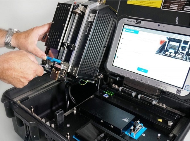
Image Credit: AMETEK Spectro Scientific
FieldLab
A New Technique: Filtration Particle Quantification Combined with EDXRF
The FieldLab is a durable, portable expeditionary fluid analysis instrument that enables field operators to collect comprehensive, mobile lubricant samples. The battery-powered device provides thorough lubricant assessment for condition monitoring and quick findings, allowing for informed maintenance decisions.Understanding all of the current approaches enables a clearer understanding of how and why the FPQ with EDXRF was created.
The FieldLab Commercial, as defined in ASTM D8127: Standard Test Method for Coupled Particulate and Elemental Analysis using X-ray Fluorescence (XRF) for In-Service Lubricants, is a one-of-a-kind system design that interprets machine failure and root cause analysis through a two-step process that combines a modified pore blockage technique with an XRF Analyzer.
This includes both the FPQ and XRF devices in the overall oil monitoring system. The filter is placed into the XRF. This rapid technique can screen out samples with high particle counts before performing a full 16-element XRF analysis on the resulting sample filter.
Integrated Particle Quantifier (FPQ) and XRF Device
The improved pore blockage approach has been dubbed "Filtration Particle Quantification" (FPQ). The FPQ employs a syringe to drive a 12 ml oil sample through a polycarbonate filter with about 30,000 4-um diameter holes, ensuring continuous flow.
The pressure drop across the filter, measured with reference to ambient pressure, is used to quantify particles from >4 um to ~1 million particles/ml.
This is accomplished primarily by employing a modified filter design as opposed to a typical pore blockage device. This new unique dual dynamic architecture enables a significantly larger particle count range (x50) beyond the point where particle swapping and saturation occur.
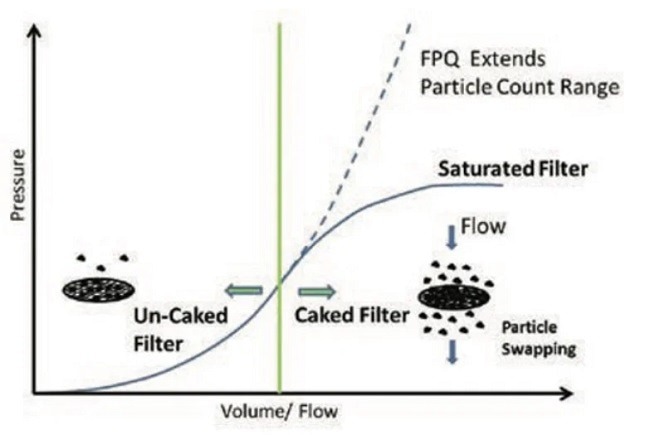
Image Credit: AMETEK Spectro Scientific
Once the analysis is completed, the filter is sent from the FPQ to the XRF device. Due to the particle swapping phenomena, the FPQ and XRF have a strong calibration relationship. The FPQ and XRF devices employ a set of distinct criteria and calibrations to ensure precise elemental quantification of particles up to 1 million particles/ml.
This technique, together with the proprietary filter, solves the problem with the oil cup analysis that most XRF instruments use.
This novel filter design confines particles to a narrow area of the filter, allowing the focused X-ray beam to concentrate its energy on those particles. The equipment detects up to 16 elements using an X-ray tube with a Rhodium target, a maximum voltage of 50 kV, and 122 eV FHM resolution at 5.9 keV.
Summary
The FPQ, with its revolutionary dual dynamic filtration technology, can handle a wide range of lubrication applications with different wear levels. The particle count utilizing the FPQ filter is consistent with known direct imaging particle counts.
The subsequent elemental concentration obtained from the FPQ filter via XRF analysis correlates well with ICP differential acid digestion.
The combined particle count and elemental concentration identify shifting wear rates and potential underlying causes of lubrication system problems. Particle count and elemental concentration offer an accurate elemental breakdown of particles caught and quantified on the filter.
This process removes many of the issues associated with previous techniques, including particle size detection and the resistant character of many lubricants used in heavy-duty industrial applications.

This information has been sourced, reviewed and adapted from materials provided by AMETEK Spectro Scientific.
For more information on this source, please visit AMETEK Spectro Scientific.