The droplet size of the fuel droplets produced by injector systems plays a central role in the control of the efficiency of the combustion process and the production of harmful emissions. As the droplet size decreases the available surface area for oxygen increases, thereby optimizing the combustion process and reducing emissions.
The design and control of the fuel injector is thus paramount in obtaining optimal power output at minimized fuel consumption and emissions for present day advanced engines.
Fuel Injection Systems
A fuel injector is a spring-loaded needle valve that's opened by an electrical solenoid. As current flows through the coil the valve opens against the pressure of the spring. The pulse width (i.e. the time the valve stays open) is determined by the Engine Control Unit (ECU). The ECU sets the pulse width according to the required engine load, ranging from below one millisecond (msec) at idle to above 20 msec at high loads.
During the pulse, flow through the injector is up to 500 cm/min. In a direct injection engine, the fuel injector is positioned such that the mixed fuel is sprayed directly into the combustion chamber. As fuel passes the orifice of the injector, the kinetic energy of the fuel is used to cause atomization on the other side of the orifice. Thus, as pressure increases on the inlet side of the orifice the droplet size decreases on the outlet side thereby increasing the efficiency of the combustion process.
Characterizing Fuel Sprays Using Laser Diffraction
Assessing the particle size produced by fuel injector systems is extremely demanding. The technique of laser diffraction provides a flexible and rapid method for the assessment of the spray droplet sizes. However, traditional laser diffraction systems typically allow data acquisition speeds of around 500 Hz (one measurement every 2msec) and do not provide the time resolution required for injector studies.
The Malvern Panalytical Spraytec has been specifically designed for the measurement of sprays and is capable of scan rate of up to 2500 Hz (one measurement every 0.4 msec). This allows information for each firing of an injector to be obtained.
Case Study - Injector Measurements Using the Spraytec Laser Diffraction System
The output of a standard production-type direct injection system was measured as a function of the injection pressure using the Malvern Panalytical Spraytec diffraction system.
The Experimental Setup
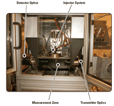
The experimental setup used in this case is shown in figure 1. The Spraytec system was integrated within a custom-designed containment system with a 500 mm distance between the transmitter and detector systems.
The system was equipped with a 200 mm lens, allowing the detection of particles with a 1400 micron size range at an acquisition rate of 2500 Hz. The optics were protected with an air purge thus preventing the deposition of fuel on the system during measurements.
|
|
|
Figure 1. Spraytec set-up for the droplet size measurement of a fuel injector. In this case the injector can be positioned at different distances from the measurement zone.
|
Particle Size Pressure Dependence
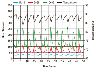
A time history showing the evolution of the particle size over time for operation of the injector at 3 bar pressure is shown in figure 2. This gives a convenient overview of the behavior of the injector and allows the reproducibility of the injector output to be assessed.
Each injection pulse is identified by a drop in the laser light transmission and an increase in the measured particle size in this case the Dv10 (size below which 10% of the volume of material exists), Dv50 (median particle size) and Dv90 (size below which 90% of the volume of material exists) are shown. The results show that fine particles remain in the measurement zone between each of the pulses, hence the transmission does not return to 100%.
|
|
|
Figure 2. Time history showing the evolution of the Dv10, Dv50 and Dv90 during the firing of a commercial injector system. In this case the injection pulse width was set at 2ms.
|
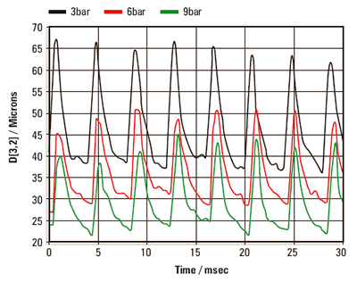
Figure 3 shows a comparison of the Sauter Mean diameter (D[3,2]) measured at 3bar injection pressure with that observed at 6bar and 9bar. As expected, the particle size decreases as the injection pressure is increased.
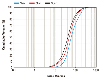
This is shown more clearly in figure 4 where the average particle size distributions are shown for each injection pressure. This reduction in particle size is related to increases in burning efficiency during engine operation.
|
|
|
Figure 3. Comparison of the particle size observed at different injection pressures for the repeated firing of the injector system.
|
|
|
|
Figure 4. Average particle size distributions obtained for each injection pressure. These averages are automatically calculated by the Spraytec software at the end of each experiment.
|
High Concentration Measurements
The measurements described above are for a relatively low concentration injector system. Some fuel injectors generate spray concentrations high enough to interfere with diffraction measurements due to errors caused by multiple scattering. However, this is automatically corrected for within the Spraytec software using a patented multiple scattering model, allowing measurements at extremely high spray concentrations.
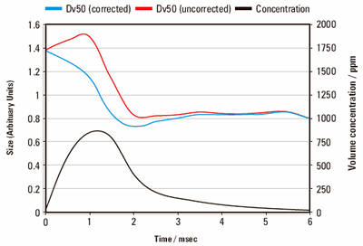
An example of the importance of multiple scattering is shown in figure 4.This illustrates the evolution of the median droplet size during a single fuel injector pulse. As expected, the droplet concentration at the beginning of the pulse increases rapidly to its peak value after which it asymptotically decreases towards zero.
Correspondingly, the median droplet size (corrected for multiple scattering) is at its largest at the highest concentration, which is consistent with the mechanics of droplet formation in this case. By contrast the uncorrected result indicates that the droplet size is largest at the initiation of the event, and decreases irrespective of the concentration (an indication of the load on the nozzle). This error is directly attributable to a multiple scattering condition where the result is artificially reduced due the droplet scattering that occurs as the concentration increases.
|
|
|
Figure 5. Time history recorded for a single firing of a high-concentration injector system. Significant errors are seen when the effects of multiple scattering are not taken into account (blue curve), especially at high concentrations.
|
Conclusion
The droplet size and size distribution produced by fuel injection systems is an important parameter in defining the efficiency and emissions output of an automotive engine. The technique of laser diffraction provides a robust means of measuring the droplet size produced by different injector systems.
The combination of fast data acquisition, purged optics and the patented multiple scattering algorithm makes the Malvern Panalytical Spraytec ideally suited to accommodate the demands encountered during measurement of droplet sizes from fuel injectors. This can lead to a better understanding of the spray dynamics and the factors important in defining engine efficiency.

This information has been sourced, reviewed and adapted from materials provided by Malvern Panalytical.
For more information on this source, please visit Malvern Panalytical.