Flaw detection is the most commonly used technique among all the applications of industrial ultrasonic testing. Generally, sound waves of high frequency are reflected from flaws and generate clear echo patterns.
Portable instruments record and display these echo patterns. Ultrasonic testing is a safe testing method that is widely used in various service industries and production process, particularly in applications where welds and structural metals are used. The paper gives an overview of the theory, practice and application of ultrasonic flaw detection.
Fundamental Theory
Sound waves are mechanical vibrations that pass through a medium such as liquid, solid or gas. These waves pass through a medium at a particular velocity in an expected direction. When these waves bump into a boundary having a different medium, they are transmitted back. This is the principle behind ultrasonic flaw detection.
Frequency, Velocity and Wavelength
Most ultrasonic flaw detection applications use frequencies between 500 KHz and 10 MHz per second. At frequencies in the megahertz range, sound energy travels easily via most common materials and liquids, but does not pass efficiently via air or similar gasses. Also, sound waves of different types travel at different rate of velocities.
Additionally, wavelength refers to the distance between two subsequent points in the wave cycle as it passes via a medium. It is related to velocity and frequency. In ultrasonic flaw detection and ultrasonic thickness gaging, the minimum limit of detection is one-half wavelength and the minimum measurable thickness is one wavelength, respectively.
Modes of Propagation
In solids, sound waves can be present in different modes of propagation that are characterized by the type of motion involved. The common modes used in ultrasonic flaw detection are shear waves and longitudinal waves.
Variables that Limit Sound Transmission
When compared to soft, heterogeneous or granular materials, hard and homogeneous materials are able to reflect sound waves more efficiently. Three factors, such as beam spreading, attenuation and scattering, control the distance a sound wave will pass in a particular medium.
Reflection at a Boundary
The amount of reflection coefficient or energy reflected is associated with the relative acoustic hindrance of the two materials. In ultrasonic flaw detection applications, metal and air boundaries are commonly seen, wherein the reflection coefficient reaches 100%. This is the basic principle involved in ultrasonic flaw detection.
Angle of Reflection and Refraction
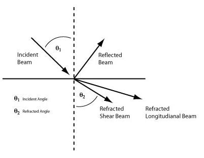
At ultrasonic frequencies, sound energy is extremely directional and the sound beams employed for flaw detection are clearly defined. As per the Snell's Law of refraction, sound energy transmitting from one material to another will bend. A beam that is traveling straight will travel in a straight direction; however, a beam that hits a boundary at an angle will bend.
Ultrasonic Transducers
A transducer is an instrument that is capable of converting energy from one state to another. Ultrasonic transducers can transform electrical energy into sound energy and vice versa.
For ultrasonic flaw detection, standard transducers employ an active element that is made of either a polymer, composite, or piezoelectric ceramic. When an electrical pulse of high voltage is applied to this element, it vibrates through a particular spectrum of frequencies and produces sound waves. When an incoming sound wave vibrates this element, it produces an electrical pulse.
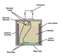
Figure 1. Cross section of typical contact transducer
In flaw detection applications, five types of ultrasonic transducers are usually employed. They include contact transducers, immersion transducers, delay line transducers, angle beam transducers, and dual element transducers.
Advanced Ultrasonic Flaw Detectors
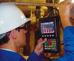
Panametrics-NDT Epoch series are ultrasonic flaw detectors that are compact and portable instruments based on microprocessor. They are ideal for shop and field applications and display an ultrasonic waveform that is easily understood by a trained operator, who detects and classifies the flaws in test pieces. The series comprises a waveform display, an ultrasonic pulser/receiver, a data logging module, and software and hardware for signal capture and analysis. In order to optimize the performance of transducer, pulse amplitude, damping and shape can be controlled. Likewise, in order to signal-to-noise ratios, receiver gain and bandwidth can be modified.
Procedure of Ultrasonic Flaw Detection
A trained operator can identify particular echo patterns related to the echo response from representative flaws and good parts. This can be done by utilizing correct reference standards and accepted test procedures along with a good knowledge of sound wave propagation. Two calibration standards such as straight beam testing and angle beam testing are used in ultrasonic flaw detection. The latter technique is commonly used in weld inspection.
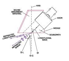
Figure 2. Typical angle beam assembly
Conclusion
Ultrasonic flaw detection is a comparative method. Although some analog-based flaw detectors are still being produced, most modern instruments employ digital signal processing to promote enhanced stability and accuracy.

This information has been sourced, reviewed and adapted from materials provided by Evident Corporation.
For more information on this source, please visit Evident Corporation.