Sponsored by GGBJan 14 2022
Metal-polymer bearings have seen success as substitutes for conventional leaded bronze or bi-metal bearings in numerous lubricated applications. Until recently, PTFE-based metal-polymer plain bearings were incapable of matching the assembled dimensional precision of metallic alloy bearings.
This limitation significantly restricted their use in applications where it is necessary to control shaft clearance to maintain operational efficiency, reduce noise or limit vibration and harshness.
To overcome this limitation, GGB commissioned a project aiming to develop a metal-polymer bearing solution that can be machined on installation, improving internal diameter control while simultaneously preserving the tribological benefits linked to the presence of a self-lubricious PTFE top layer.
This article details GGB’s development experience, focusing on challenges faced and lessons learned.
GGB’s internal validation testing process is described, as well as the distinct characteristics and performance advantages of this new product concept. The article concludes with two case studies that feature practical examples of metal alloy plain bearings being successfully replaced.
These case studies incorporate customer feedback and experience – the result of field-based performance evaluation by two key development partners, representing different lubricated applications and markets: gear pumps and compressors.
Context
It has been over fifty years since the invention of the first self-lubricated metal-polymer plain bearing. Since their initial development, their use continues to grow, with new lubricated applications and fluid power systems being developed all the time.
In many applications, these self-lubricating bearings have superseded traditional metallic alloy or rolling element bearings.
Their popularity is primarily linked to the unique combination of tribological characteristics offered by the multi-layer composite structure (Figure 1) comprised of:
- A metal backing - typically steel
- A sintered porous bronze layer (~30% porosity) filled with a custom-formulated PTFE blend
- An overlaid thin top layer of the same PTFE blend, impregnated into the bronze
- The filler choice and proportion largely determine important bearing properties. These properties include friction, wear, erosion and fatigue resistance.
Engineers tend to prefer this material configuration due to the lower friction offered by the PTFE layer – versus that of metal alloy bearings - and its capacity to self-lubricate during periods of insufficient or marginal lubrication.
The lower stiffness of the self-lubricious polymer top layer also encourages the formation of a fluid film due to elastohydrodynamic (EHD) effects. This type of bearing is, therefore, far more tolerant of edge loadings and shaft misalignments than its metal counterparts.
While this offers notable performance advantages, metal alloy plain bearings remain a common choice in applications requiring tight tolerances. The homogeneous composition of metal alloy bearings means they can be machined in the assembly to a considerable depth without impacting the sliding surface’s performance.
Machining a conventional PTFE-based metal-polymer bearing, however, is not advisable due to the limited thickness of the PTFE layer (generally 5-25 μm) and the performance risks from exposing high proportions of the underlying bronze.
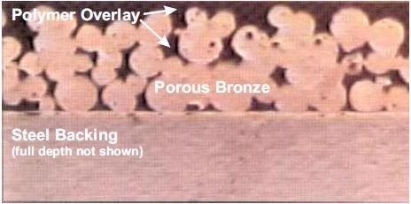
Figure 1. Typical cross section of a PTFE based metal polymer bearing. Image Credit: GGB
Table 1. Friction and dimensional characteristics by bearing type. Source: GGB
| |
Metal Alloy |
Traditional Metal Polymer |
Desired Solution |
| Friction |
Poor |
Good |
Good |
| Dimensional Precision |
Good |
Poor |
Good |
Table 1 summarizes the typical trade-off between these product types, in terms of respect to tolerances and friction.
Efforts to limit ID variation of metal-polymer bearings have historically depended on secondary sizing techniques. These techniques involve the insertion of a specially designed, oversized pin through the assembled bore to plastically alter the diameter and reduce the bearing wall thickness.
When working with high pin interferences and under aggressive conditions, however, this technique may present possible risks to bearing performance. It is important to ensure that comprehensive validation testing is performed if this technique is employed.
Previous work has demonstrated that a notable level of burnishing can take place without a measurable reduction in wear life when working with compressors.1 This method produces dimensional tolerances that have not historically matched the precision of a machined metal alloy bushing.
It is only possible to achieve optimized performance in some applications through the precise control of clearances.
It has been demonstrated that compressors fabricated with metal-polymer bushings can provide efficiency increases as high as 3% versus metallic bearings with an identical clearance level.2
Similar aspirations around enhanced dimensional tolerances have been expressed by gear pump manufacturers who continually seek a combination of reduced noise, minimal vibration and improved mechanical efficiency.
Project Detail
GGB has embarked on a pioneering development program to help meet these market requirements. The company has developed a low friction, metal-polymer bearing designed for use in oil lubricated applications.
As well as providing beneficial properties, this lubricant can be machined after assembly for improved dimensional precision.
A central consideration throughout this process was to leave a sufficient coating of filled PTFE intact on the surface after machining to maintain the desired performance benefits of a traditional metal-polymer.
Two core technical challenges - which necessitated a delicate balance of material and process development - were presented when attempting to achieve this project’s goals.
It was necessary to devise a means of producing a suitably thick PTFE layer above the porous bronze structure.
GGB’s conventional processing technology relies on the coagulation of PTFE aqueous dispersions and fillers in order to produce a wet, polymer blend that can be easily impregnated into the bronze’s pores.
Unfortunately, this approach is limited to a maximum overlay thickness of 30 μm due to the need to drive off any moisture and solvents present within the paste and associated risks of blistering above this thickness.
Initial calculations were based on application engineering experience with gear pumps. These calculations suggested that 100 μm was the minimum overlay thickness necessary in ensuring sufficient machining allowance and a fully functional operating layer.
With this in mind, the target design thickness of the functional operating layer following machining was determined to be 5-60 μm.
It was necessary to develop and optimize a suitable PTFE and filler formulation that offered sufficient compatibility with the process method while being suitable for clean machining with minimum burrs.
It was also important that this formulation offered a satisfactory bearing performance in oil in terms of its resistance to fatigue, wear, and erosion.
From concept to solution, this project followed a series of standard procedures and milestones in line with a disciplined stage-gate process. GGB’s standard development protocol is comprised of six key stages (Figure 2).
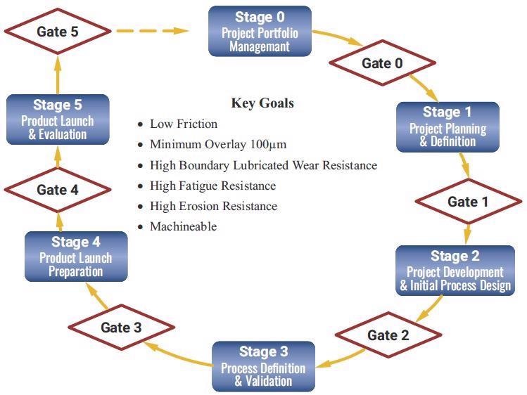
Figure 2. GGB's product development cycle and generic goals. Image Credit: GGB
Stages 0 and 1 of the protocol are essentially concerned with the initial project evaluation and planning work. The general project objectives were established, and these were refined into specific, measurable development targets.
Minimum acceptable performance limits were set for the formulation’s friction, wear, fatigue and erosion properties. These were each quantified and defined relative to the known performance of a reputable benchmark metal-polymer material tested under GGB’s standard conditions.
It was decided that an ‘equivalent’ performance to this benchmark product would be a satisfactory goal.
Desirable secondary product characteristics included temperature and chemical resistance, PTFE layer adhesion and the material’s potential to be formed into different, routine bearing forms and geometries, for example, washers, cylindrical or flanged bushes.
Issues regarding the product’s ‘machineability’ also arose, including the need to limit bronze exposure, minimizing the risk of seizure or reduced bearing life,
It was also important to ensure that polymer thickness could be controlled across the machined ID or alternatively confirm that thickness variation had no negative impact on performance.
It was also necessary to consider traditional machining considerations, for example, the chance of galling or tearing and its effect on surface quality or finish.
Stages 2 and 3 encompassed the primary development activities, with a great deal of emphasis placed on identifying, verifying and validating an appropriate material and process.
This feasibility stage involved the full range of known PTFE processing methods being evaluated in terms of their capacity to allow thick layer formation. PTFE skiving seemed to be the most promising route, enabling the formation of continuous cured lengths of filled polymer tape.
However, after significant time and effort, this process’s robustness was deemed to be insufficient due to the tape’s toughness and issues with impregnating into the pores of the bronze.
It was noted that either an inadequate depth of impregnation was possible, or extreme material stress led to surface blistering or crack formation along the top of the bronze layer.
In either instance, this presented a potential risk of material delamination or galling during bearing or machining operation. The project initially stalled after failing to eliminate these risks, necessitating a complete review of its viability.
The decision was made to initiate a collaborative partnership with a specialist in PTFE tape manufacturing to develop and optimize the production of a highly filled PTFE tape in an uncured form.
It was determined that uncured PTFE tapes offer much higher plasticity and flexibility, improving their capacity for impregnation with minimum stress on the material.
Using this approach required the implementation of a second process to cure the filled PTFE layer following impregnation, ensuring an optimized sliding surface with ideal molecular structure and tribological properties.
Initial trials highlighted that ease of tape impregnation was closely linked to the polymer blend’s formulation. A number of experimental blends were tried and tested, based on GGB’s extensive experience with effective filler packages for oil-lubricated environments.
The formulations that were successfully impregnated were initially subjected to laboratory machining trials on a lathe, followed by comprehensive tribological screening.
One candidate outperformed the others, exceeding every tribological performance expectation. The optimum composition consisted of a PTFE matrix filled with two key ingredients. One of these ingredients was calcium fluoride - a reinforcing filler common in many of GBB’s lubricated products and known to function effectively in oil.
Extensive testing was undertaken, confirming that it was possible to produce material strip and manufacture bearings with an appropriate overlay thickness and quality. The material design was then frozen.
With the material frozen and in place, the project moved on to Stage 3, which sought to establish and validate a robust, capable process for high volume material and bearing manufacturing. This phase involved substantial investment and modification of current processing lines.
Once the modified line was in place, a series of studies were undertaken to optimize the production of the composite strip in continuous coil form.
These studies also sought to understand the complex interaction among and between key parameters such as temperature, applied pressure, line speed, tape thickness and tape tension on the material’s dimensional and tribological characteristics.
This process was time-consuming because each iteration required a large number of material variants to be manufactured and tested across a wide range of test rigs and conditions.
With the optimum process window established, its robustness was tested and validated via a series of repetitive high-volume material and bearing manufacturing trials. These trials were followed by comprehensive testing with a view to confirming product stability.
A significant number of unexpected problems and challenges occurred during the project, though it was possible to establish a plan to systematically address and resolve these issues. These problems extended the project timeline, however, causing some delays.
Centering the Voice of the Customer
While early laboratory testing suggests this prototype solution may satisfy the project objectives around bearing performance and machinability, it was noted that independent evaluation by a possible end-user would offer invaluable input and confirm whether the approach was viable.
GGB invited a major gear pump manufacturer and a major scroll compressor manufacturer to become development partners on the project, affording them the opportunity to assess and help refine the product.
Both these customers were exploring alternative bearing options to their existing metal alloy bearings due to environmental pressure to eliminate lead.
These applications offered two very different and highly challenging operating environments (Table 2), each using significantly different bearing geometries, representing large and small diameter parts.
Table 2. Comparative operating conditions and bearing requirements. Source: GGB
| |
Scroll Compressor |
Gear Pump |
| Bearing diameter [mm] |
40 – 60 |
8 – 42 |
| Load [MPa] |
3 – 6 |
25 – 50 |
| Speed [m/s] |
8 – 11 |
2 – 5 |
| Lubricant |
Oil (2%) + Refrigerant |
Oil |
| Clearance [µm] |
70 – 100 |
25 – 50 |
| Temperature [°C] |
65 – 107 |
80 – 120 |
Case Study 1: Gear Pump Bearings
The gear pump or motor is an efficient and compact high-pressure unit common in a diverse array of fluid power applications.
The gear pump’s underlying principles are simple: two intermeshed gear rotors draw in fluid on one side before forcing this out the other side. These pumps see wide-ranging use, particularly in the agriculture, automotive, construction, aerospace and mining industries.
Gear pumps in the automotive industry are employed in power steering systems, in off-highway and construction equipment, and tractor power take-off systems.
A gear pump’s performance is highly dependent on gear rotors’ design and dimensional precision, as well as the chambers in which these rotate and the bearings that support the rotors.
Metal-polymer bearings are a popular choice in high-duty pumps. These are lubricated by the pumped fluid and operate under hydrodynamic conditions with extremely thin lubricant films.
Low wear rate is essential under these circumstances since wear affects the relative positioning of the gear rotors and, therefore, the pump efficiency.
The high specific bearing loads due to pump delivery pressure is a significant factor here, and the bearing surface is exposed to dynamic loading from gears’ interaction. This requires the bearing material to demonstrate adequate fatigue strength.
There is also a danger of cavitation erosion occurring on the bearing surface. To avoid this, the bearing must provide optimum properties while maintaining very low friction characteristics.
The pump design chosen represented the new generation of ‘silent’ gear pumps. These pumps require critical control of specific bushing block dimensions to minimize vibration, noise and harshness.
Figure 3 shows the assembled tolerances which could not be satisfied with traditional thin layer PTFE metal-polymer bearings. To ensure the required precision for supporting the gear rotors, the customer was dependent on the machining of four leaded bronze bearings assembled in two aluminum binocular blocks.

Figure 3. Critical dimensions and target tolerances on bushing block assembly. Image Credit: GGB
In this instance, GGB had complete responsibility for manufacturing and supplying the bushing block sub-assembly, meaning that all bush assembly and machining experience was acquired first hand, under fully automated production conditions.
First, the crude aluminum block was machined, and the bearings were assembled. Every installed bearing’s internal diameter was reamed to size simultaneously before two parallel grooves were cut. The exterior of the housing was then machined to its final form and size relative to the bearing ID.
A standard machining setup and conditions were utilized for leaded bronze bearings, but preliminary trials with GGB’s machinable metal-polymer prototype were found to be disappointing in terms of their finished dimensions and quality.
A number of issues were encountered, including machined polymer swarf remaining attached to the bore, poor cylindricity and an uneven PTFE sliding layer around the bore – the latter also posing an issue with sporadic localized exposure of bronze.
A study was initiated with a University department that specialized in machining practices, with a view to leveraging its experience and expertise to help establish a series of machining and tooling design guidelines for this type of product.
At the same time, a local study was undertaken on the bushing block automated machining and assembly line by GGB process engineers, aiming to optimize the machining setup and related conditions.
This work led to all identified issues being systematically resolved, but it became quickly evident that this metal-polymer solution was not destined to be a straightforward ‘drop in’ replacement for any metal alloy bearing.
Instead, the end-user would require a degree of process refinement and validation trials – including a specific focus on tooling setup and alignment due to its limited overlay thickness of 100 μm.
Machining experience for this application currently equals more than four million assembled bushes (two million bushing blocks), and both the product concept and process have been shown to be capable of meeting the customer’s dimensional specifications in full.
A dispersion of 0.08 mm has been achieved (representing a Cpk of 1.67) for an internal diameter tolerance of 0.015 mm.
The bore surface roughness is generally 1.2 μm Ra after machining. This is marginally higher than expected from a metal alloy bearing and does not present any problems due to the material’s conformable, soft and lubricious nature.
Results from initial laboratory testing of prototypes in the pump were encouraging enough to capture the customer’s interest, prompting them to commit to the development project.
The customer performed extensive field testing, confirming the expected performance advantages in terms of friction improvements and superior seizure resistance versus leaded bronze, particularly during start/stop conditions.
It was concluded that the lower modulus polymer layer offered a damping effect which also resulted in noise reduction.
Case Study 2: Scroll Compressor Bearings
The role of scroll compressors is to compress air or refrigerant, prompting their frequent use in central heating pumps, automotive air conditioners and commercial air conditioning systems.
Their fundamental operating principle is based on relative motion between two spiral scrolls, which trap and pump pockets of fluid between the scrolls. To ensure efficiency, some types of scroll design necessitate the implementation of extremely tight tolerances in relation to bore position and bearing clearance.
The selected development partner employed machined aluminum alloy bearings that contained lead while actively exploring lead-free options. This issue was compounded by changes in regulations regarding refrigerants, necessitating robust bearing performance to accommodate increased pressures.
Because metal alloy offerings struggled to accommodate the loads in question, the design engineers looked into the option of metal-polymer bearings. Poor efficiency resulting from loose tolerances continued to present a barrier that needed to be overcome in order to adhere to governmental SEER ratings, however.
It was also specified that the bearing solution should be:
- Compatible with the refrigerant and oil
- Able to survive three stringent test regimes:
- Lubrication-free, repetitive dry start testing (heavy contact / short periods)
- Boundary / mixed film lubrication (light contact / extended duration)
- Hydrodynamic testing (ideal condition)
- Resistant to fatigue
- Resistant to erosion
- Resistant to seizures
- Tolerant to edge loading and debris
The initial prototype was comprised of two upper bearings supporting the main housing and orbiting scroll of a 15 Ton compressor. These were selected for prototype testing.
Figure 4 shows the general design and bearing positions. Early test results were successful, prompting the development partner to expand the trials to include the higher loaded 30 Ton compressor.
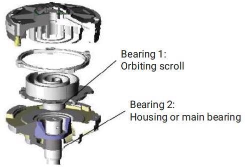
Figure 4. Scroll compressor concept and test bearing locations. Image Credit: GGB
In contrast to Case Study 1, this application did not use automated machining and instead relied on a manual lathe machining process undertaken by the customer.
The customer carried out a series of demanding laboratory compressor tests over the course of two years, pushing the prototypes to their limits to identify the most frequently encountered failure modes. Deliberately aggressive and accelerated testing demonstrated the potential for fatigue damage and erosion in this environment, but it was noted that once initiated, these were not progressive.
This material was found to excel in all areas when used under standard conditions.
Product Attributes
The initial product concept has continuously evolved over the course of the 8-year project. Incremental refinements were completed systematically, based on feedback and recommendations from the project’s development partners.
The resulting product - DTS10™ - confidently improves upon the performance capabilities of conventional metal-polymer bearing technology as a result of its dimensional tolerance. DTS10™ provides a practical alternative to metal alloy bearings in a wide range of applications.
The DTS10™ bearing structure (Figure 5) offers a nominal overlay thickness of 0.12 mm (0.1 mm minimum). This can be machined to tight tolerances without sacrificing the typical benefits of metal-polymer bearings, so long as this is done under carefully controlled conditions.
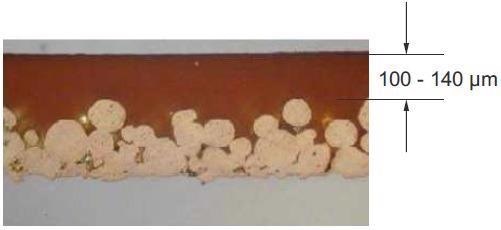
Figure 5. Cross section structure of DTS10™. Image Credit: GGB
Bearing Performance Attributes
The performance of DTS10™ was evaluated using standard GGB test rigs and test conditions. All key bearing properties were measured and compared against the reference metal-polymer product specified in the initial project objectives.
The impact of machining on the material properties was verified where possible, revealing no notable or negative performance impact when recommended machining practices and conditions were adhered to.
Friction
Tribometer testing under various dry and oil-lubricated conditions confirmed low levels of friction consistent with a sliding surface whose primary ingredient is PTFE – a natural lubricant.
Figure 6 and Figure 7 examine the friction performance of DTS10™ with increasing load, comparing this to a standard bi-metallic bearing material under dry and lubricated conditions, respectively.
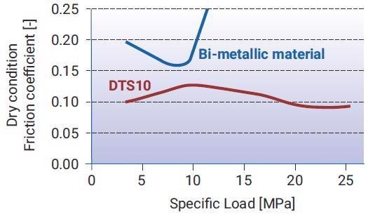
Figure 6. Friction - load relationship for DTS10™ and a standard bi-metallic baring material, under dry conditions. Image Credit: GGB
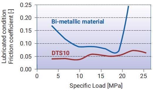
Figure 7. Friction - load relationship for DTS10™ and a standard bi-metallic bearing material, under oil lubricated conditions. Image Credit: GGB
Lower friction, higher load capacity and enhanced seizure resistance associated with the self-lubricating metal-polymer bearing were noted in every instance.
Figure 8 shows the friction compared against the target metal-polymer reference defined in project objectives.
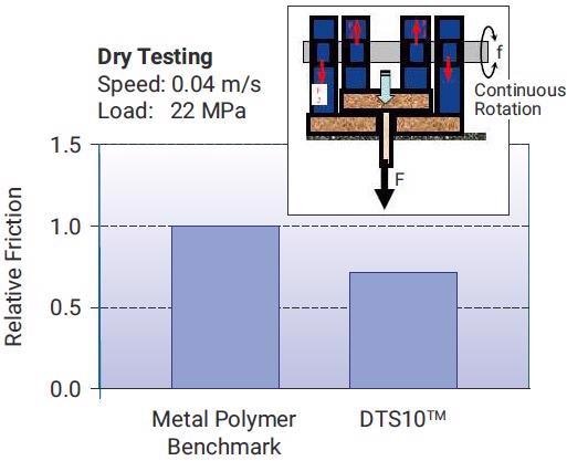
Figure 8. Relative friction (dry) between DTS10™ and Metal-polymer Benchmark performance. Image Credit: GGB
Boundary Lubricated Wear Resistance
The durability and wear resistance of DTS10™ were found to be superior to the current industry metal-polymer benchmark. This was the case in both its machined and non-machined form. Figure 9 shows the boundary lubricated wear resistance of DTS10™ versus the metal-polymer benchmark.
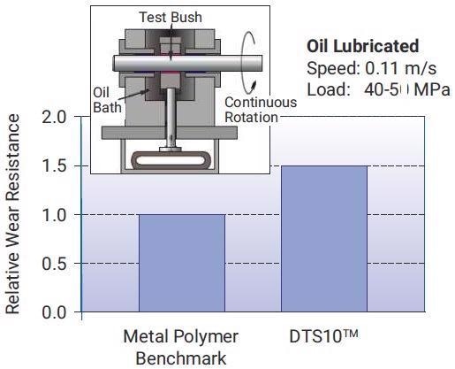
Figure 9. Relative wear resistance under steady load, boundary lubricated conditions. Image Credit: GGB
Fatigue Resistance
Fatigue resistance is vital in gear pumps and scroll compressors because these components frequently see bearings subjected to high-frequency dynamic loads in oil.
Resistance to fatigue damage was found to be exceptionally high for DTS10™ under this regime, enduring over 16 million cycles before there was any evidence of damage – a figure that is approximately four times higher than the current metal-polymer standard.
Figure 10 displays the fatigue damage of DTS10™ relative to the metal-polymer benchmark performance.
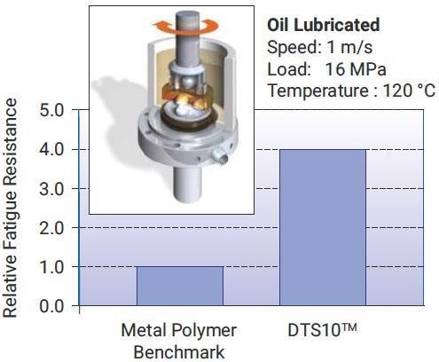
Figure 10. Relative fatigue resistance between DTS10™ and the metal-polymer benchmark performance. Image Credit: GGB
Cavitation Erosion Resistance
Measurements were taken of the bearing’s ability to resist cavitation erosion. These were compared with the project benchmark metal-polymer product. Figure 11 displays the relative cavitation erosion resistance.
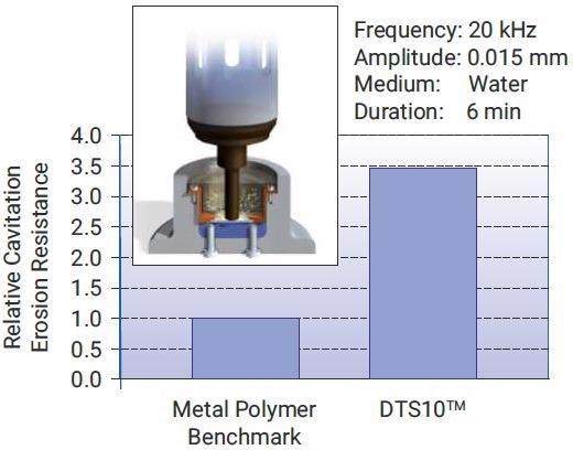
Figure 11. Relative cavitation erosion resistance between DTS10™ and the metal-polymer benchmark performance. Image Credit: GGB
Corrosion Resistance
Aggressive oils - particularly oils containing high levels of sulfur - are able to chemically attack bronze in bearings. Laboratory corrosion testing of DTS10™ involved the use of an incredibly aggressive standard test oil that had been heated to 140 ºC.
These tests revealed that the product represented a notable improvement in chemical resistance versus the majority of other metal-polymer products. This was also the case for DTS10™ in its machined form.
Figures 12a to 12c feature images which compare corrosion levels found in DTS10™ with various other reference bearing materials. These measurements were taken after 100 hours’ exposure to the heated oil.
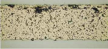
Figure 12a. Industry standard bi-metallic bearing after corrosion testing. Image Credit: GGB
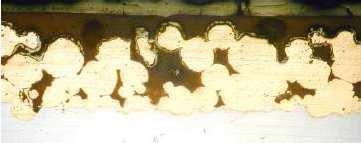
Figure 12b. Metal-polymer benchmark bearing after corrosion testing. Image Credit: GGB
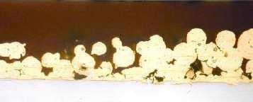
Figure 12c. DTS 10™ after corrosion testing. Image Credit: GGB
GGB testing confirmed that DTS10™ exceeded the full range of initial project performance metrics. It was found to consistently outperform the best current PTFE industry benchmark product.
Customer feedback and testing in gear pumps and compressors offer additional support for this conclusion. The product’s enhanced bearing performance stems from a combination of its carefully designed formulation and the proprietary processing technique employed during the material blend’s preparation.
Machining Characteristics
Machining trials by GGB and its customers have confirmed that the material is compatible with the majority of standard machining processes, for example, turning, reaming, broaching and milling.
Investigative trials were key to establishing recommended procedures for each process, with studies also showing that surface roughness is sensitive to machining conditions. Figure 13 highlights the impact of varying tool feed rates.
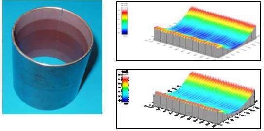
Figure 13. Influence of tool feed rate on surface roughness. Image Credit: GGB
It was also shown that rougher surfaces might lead to marginally higher start-up friction. The surface would be rapidly modified during run-in before returning to the optimum friction level. There was no evidence of other effects of surface roughness.
The low thermal conductivity of PTFE and other fluoropolymers may lead to the heating of the tool and polymer material during a high-speed cutting operation. This may result in deformation of the PTFE, as well as excessive wear of the tools.
Therefore, it is essential to employ a lubricant during machining to avoid such overheating effects. PCD (polycrystalline diamond) or coated carbide (K10) tooling is also recommended to minimize wear to tooling.
It has been demonstrated that machining the bore of DTS10™ bearings significantly improves their concentricity. Trials have also highlighted that the assembled bearing’s roundness could be as much as 16 μm or as little as 2 μm following machining.
Lessons Learned
GGB regards this project as a success. The resulting product meets or surpasses all initially agreed-upon project objectives, with testing confirming this.
There are lessons to be learned by taking time to reflect on the overall management experience. Therefore, stage 5 of GGB’s development protocol features a routine review.
The project highlighted the immense and wide-ranging benefits of working alongside third-party partners, whether these partners represent end-users or subject matter experts.
If GGB had been unwilling or unable to collaborate with other PTFE processing experts, the project would have failed at an early stage due to technical barriers not being addressed.
Suppose customers had been unwilling to provide early feedback and identify key product weaknesses. In that case, the product might have been launched prematurely for its intended applications with issues not resolved in time, severe post-launch debugging or even market failure.
The strengths and limitations of the product were well characterized prior to launch, meaning that these could be openly communicated with customers.
The nominal overlay thickness of 120 μm was shown to be a viable level for machining, providing that adequate care and control are applied. However, it is recognized that this may not be appropriate for every customer’s machining capability.
It will be essential to work alongside customers’ engineers to optimize their design and machining setup. The pursuit of higher overlay thicknesses will continue in light of this potential limitation.
The project was initially anticipated to take four years, but it actually took eight years to find and optimize a solution. This extended timeframe was due to a number of factors, including over-optimistic planning and an underestimation of the impact of arising technical issues.
The future of the project appeared to be at risk on more than one occasion, but a combination of market needs and the team’s confidence and determination to find solutions was key to convincing management to continue supporting the project.
GGB’s stage-gate process and its insistence on regular reviews were especially effective for this purpose. It guaranteed that clear communication and frequent debate took place regarding revised activities and timing.
The proprietary processing technology developed for DTS10™ - alongside the experience gained - is expected to form a robust foundation for the next generation of higher performance bearings designed for use in other operating environments, including non-lubricated settings.
Conclusion
The project’s primary goal was to develop a polymer solution that offered both the performance benefits of metal-polymer bearings and the dimensional precision of traditional bi-metallic journal bearings.
This goal was confidently met with the development and launch of DTS10™. This bearing is able to effectively exploit every benefit of the conventional metal-polymer composite structure but, thanks to its specifically formulated, thick PTFE overlay, it can also be machined on installation to ensure enhanced control of assembled tolerances.
The bush has been designed to facilitate assembly into a rigid housing; its internal diameter machined to leave between 5-60 μm of lubricious polymer above the bronze.
The polymer overlay’s formulation was specifically designed to operate in lubricated applications. Comprehensive testing by GGB and during field trials in gear pumps and scroll compressors has verified that every performance goal was met.
The coefficient of friction was also found to be very low. This is consistent with a PTFE lubricant and equates to outstanding seizure resistance and advanced operational efficiency in any fluid power system.
The material also offers impressive resistance to fatigue, chemical attack and cavitation erosion damage - all key properties to ensure that a bearing can operate effectively in an aggressive oil-lubricated environment.
These attributes and their machineability are set to expand the use of metal-polymer bearings into a number of new application spaces within the fluid power industry.
The two end users who took part in the project have also approved and adopted this solution in their existing gear pumps and scroll compressors. They are also planning on exploiting its advantages further in future projects.
References
- Michael R. Kim, Yuan H. Peng, Christopher D. Small “The Tribological Performance of Self-Lubricating Bearings Following Secondary Sizing”, July 2008.
- Christopher D. Small “The Design Aspects of Metal- Polymer Bushings in Compressor Applications”, December 2006.
Acknowledgments
Produced from materials originally authored by Derek Marsella and Souad Belmahdi from GGB.

This information has been sourced, reviewed and adapted from materials provided by GGB.
For more information on this source, please visit GGB.