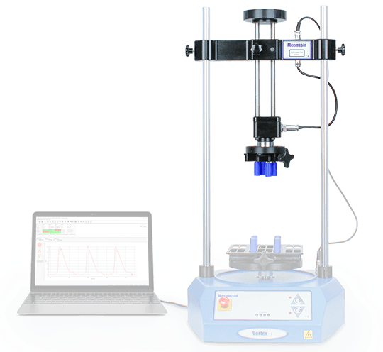
Mecmesin has introduced a semi-automated test system, called TSCC, for validating the calibration of adjustable and preset torque-limiting screwdrivers, up to 10 Nm.
With features like one-touch operation and preprogrammed tests, the TSCC system prevents result inconsistencies and repetitive strain injuries to operators, which are usually linked to manual testing.
Torque Sensors
The ITC series of interchangeable torque sensors have been particularly designed for the Vortex test system. The torque sensors have a plug-and-play feature for automatic calibration and include a wide range of capacities, from 0.3 N⋅m (2.7 lbf⋅in) to 10 N⋅m (90 lbf⋅in), to meet all kinds of requirements.

Image Credit: Mecmesin Ltd
ITC Torque Sensors
The ITC series of interchangeable torque sensors have been specifically designed for the Vortex-i and Vortex-xt test systems. The sensors can be plugged into the frame and their calibration properties are instantly detected by the tester software without any operator input.
All sensors are equipped with a ⅜″-male square drive to connect to an array of fixing tables and chucks to hold users’ samples.
To make sure that users have the best selection to fulfill all their torque testing requirements, five different sensors are now provided. All torque sensors measure from zero, spanning from 0.3 N⋅m up to 10 N⋅m.
Sensor Capacity, Range and Accuracy
Every sensor reads from zero to its complete nominal capacity, as shown below. Measurement precision is an excellent ±0.5% of the sensor capacity.
Table 1. Source: Mecmesin Ltd
| Model |
0.3 N.m |
1.5 N.m |
3 N.m |
6 N.m |
10 N.m |
| N.m |
0 - 0.3 |
0 - 1.5 |
0 - 3.0 |
0 - 6 |
0 - 10 |
| kgf.cm |
0 - 3 |
0 - 15 |
0 - 30 |
0 - 60 |
0 - 100 |
| lbf.in |
0 - 2.7 |
0 - 13 |
0 - 26 |
0 - 52 |
0 - 90 |

Image Credit: Mecmesin Ltd
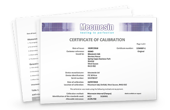
All sensors are supplied as standard with their own calibration certificate that can be traced to national standards.
Servicing and Calibration
Mecmesin also offers yearly servicing and re-calibration of torque sensors. To learn more, customers can contact one of the company’s engineers or their local national distributor.

Image Credit: Mecmesin Ltd
Overview
Torque screwdrivers have been developed to prevent over- and under-tightening by slipping when a fixed torque is applied. To make sure that torque screwdrivers perform properly and consistently, they should be validated and calibrated routinely.
Manual calibration techniques are highly time-intensive and can be affected by different operators. Not only do they make it costly to validate the huge numbers of tools but also pose a risk of repetitive strain injuries to the staff.
The TSCC is built on the Vortex-xt automated torque tester from Mecmesin. This system has been developed to prevent the variability related to manual calibration techniques and uses a pre-set speed and maximum quality certified torque cells to ensure improved precision and repeatability.
With a universal test fixture, all sizes of torque screwdrivers can be easily mounted. This ensures consistency when validating different types of tools. With intuitive and simple operation controls, a torque test can be completed by simply pushing a button. This reduces operator training and the time involved in testing.
The torque screwdriver generally takes three torque measurements for each tool in less than 30 seconds and instantly indicates the pass/fail status to the operator. The pre-set mechanism in the tool can be adjusted on the spot and retested instantly.
The side of the machine includes a handy touch-screen console that stores all the pre-programmed tests and obtains the information for export and reporting functions.
Besides this, a barcode reader is available for scanning tool IDs and these are automatically registered in the tester software for inclusion in test reports.
Key Specifications
Torque
All available sensors measure from zero to the value specified in the table below.
Table 2. Source: Mecmesin Ltd
| Model ITC |
0.3 N.m |
1.5 N.m |
3 N.m |
6 N.m |
10 N.m |
| N.m |
0.3 |
1.5 |
3 |
6 |
10 |
| kgf.cm |
3 |
15 |
30 |
60 |
100 |
| lbf.in |
2.7 |
13 |
26 |
52 |
90 |
- Resolution: 1:6500
- Accuracy: ±0.5% of full scale
- Units of measurement: N⋅m, mN⋅m, N⋅cm, gf⋅cm, kgf⋅cm, lbf⋅ft, lbf⋅in, ozf⋅in
Angle
Table 3. Source: Mecmesin Ltd
| . |
. |
| Maximum displacement |
2,440 revs |
Speed
Table 4. Source: Mecmesin Ltd
| . |
. |
| Speed |
0.1 - 20 rev/min (clockwise or counter-clockwise) |
| Accuracy |
±1% of indicated speed |
| Resolution |
0.01 rev/min |
Dimensions
Table 5. Source: Mecmesin Ltd
| . |
. |
| Maximum headroom |
505 mm (19.9") without mounting tables
448 mm (17.6") with mounting tables fitted |
| Maximum travel of adjustable carriage |
182 mm (7.2") |
| Width between columns |
280 mm (11.02") |
| Opening span of lower mounting table |
10 - 190 mm (0.39 - 7.5") |
| Opening span of upper mounting table |
10 - 78 mm (0.39 - 3.07") |
| Weight |
19.5 kg (43 lb) |
Common Specifications
Table 6. Source: Mecmesin Ltd
| . |
. |
| Maximum power requirements |
100 W |
| Voltage |
230 V AC 50 Hz or 110 V AC 60 Hz |
| Operating temperature |
10 - 35°C (50 - 95°F) |
| Humidity range |
Normal industry and laboratory conditions |
| Compensation for system movement |
No |
| Graphical presentation |
Yes |