Ambient vibration limits the resolution for all types of microscopes. The vibration diminishes the localizability of features in noticeable ways - an increasing issue for the long acquisition times and reducing scale of current imaging applications.
What is not obvious is the interplay of seismic, cable-borne, mechanical, and acoustic stimuli. Bolting equipment to a generic air-table may not be enough to realize nanoscale stabilities that are required today.
This article provides a review of isolation methods, which range from the classical to the most recent. It also spotlights the under-appreciated factors contributing to system instabilities, and provides suggestions for productive strategies for mitigation.
Conventional Air Isolators
Since the 1970s, the air table has remained a common tool for improving stability. Here, a pressurized diaphragm provides support to the table-top, while also offering a low-friction, weak-spring support that attenuates the high-frequency vibration originating from the floor.
The resulting spring-mass system presents a transmissibility curve with a characteristic resonant frequency (Fres) of 1 - 3 Hz, and amplifying the spectral components near to these frequencies (Figure 1).
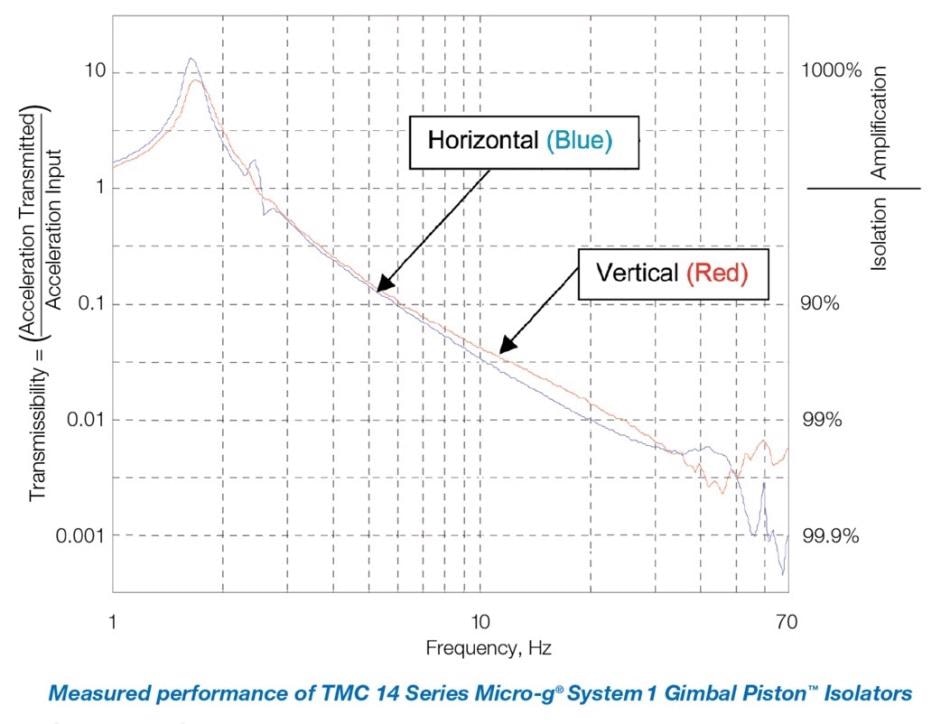
Figure 1. Conventional air isolator transmissibility curve
Piezo Technology Addresses Low-Frequency Transmissibility and Amplification
Air isolators provide good attenuation of high-frequency floor vibrational components. The isolators’ transmission of low frequencies and amplification at Fres in the 1 - 3 Hz band is problematic for use in advanced imaging techniques.
Piezoelectric technology provides responsive nano-actuation and long-term positional stability of objectives, sample positioners, and scanning probes [1]. This feature has been utilized in novel isolators that cancel out low-frequency transmitted floor excitation.
In such active vibration cancelation systems, sensors monitor and measure floor vibration continuously and the piezoelectric devices undergo expansion and contraction to deliver the nullifying forces in real-time under digital control [2].
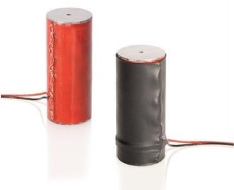
Figure 2. High-force piezo stacks
In a unique hybrid technique of particular interest for advanced microscopies, pneumatic isolation elements are combined with high-reliability piezoelectric active nullification technology to provide better combined isolation.
The strengths of both technologies are utilized in this approach. The piezoelectric active isolation handles the issue of the transmissibility and amplification of the pneumatic component at low frequencies. The pneumatic element takes care of the inevitably finite bandwidth of the active isolation technology (Figure 3).
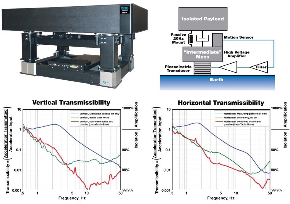
Figure 3. Comparative transmissibilities for passive vs. hybrid isolation
The Floor Is Only One Source
Tables are resonant structures. Better models have damping elements integrated into them that reduce their response to stimulus. The stimuli could be a residuum of floor vibration through the isolators, or from cable-borne, acoustic, or onboard sources including transformers and fans. Mitigation techniques include:
- Leverage structural nodes
Mounting isolators on the node-lines of the lowest-order resonant mode can reduce the excitation. (As per Chladni analysis, the node-lines are located approximately at 20% of a rectangular leaf’s length from the short sides of the leaf.) This can also be the location to wrap cables that transmit vibration.
- Reduce coupling of acoustic room-modes
A box on the table isolates optics from obvious air currents, but acoustic disturbances have to be dealt with differently. A helium-filled covering can reduce the noise spectral density through reduced path fluctuations [3]. In contrast, airborne disturbances are coupled directly to the isolated platform. For a typical laboratory measuring 10 meters in length, the least longitudinal room mode frequency is f = c / 2L. Taking the speed of sound c to be 340 m/sec, f is approximately 17 Hz. Although this is in subaudible range, it can cause problems for sensitive equipment. Mitigation strategies include usage of separate frames for covering boxes and decreasing their surface area as shown in Figure 4. In addition, “bass traps” from recording-studio engineering can also be helpful.
![Before/after quiescent spectra of an advanced microscopy apparatus with “isolation box” attached or removed from the table-top [4]. Top: accelerometer data. Bottom: Data observed at AFM tip. [Courtesy Thomas Perkins, JILA, National Institute of Standards and Technology and University of Colorado, Boulder].](https://d12oja0ew7x0i8.cloudfront.net/images/Article_Images/ImageForArticle_13496_4469035554038193827.jpg)
Figure 4. Before/after quiescent spectra of an advanced microscopy apparatus with “isolation box” attached or removed from the table-top [4]. Top: accelerometer data. Bottom: Data observed at AFM tip. [Courtesy Thomas Perkins, JILA, National Institute of Standards and Technology and University of Colorado, Boulder].
Additional Application Photos of LaserTable-Base™
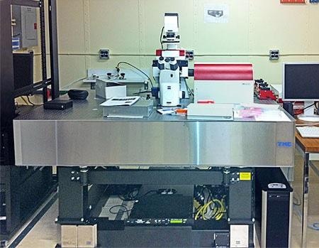
Photo courtesy of IBM Corporation
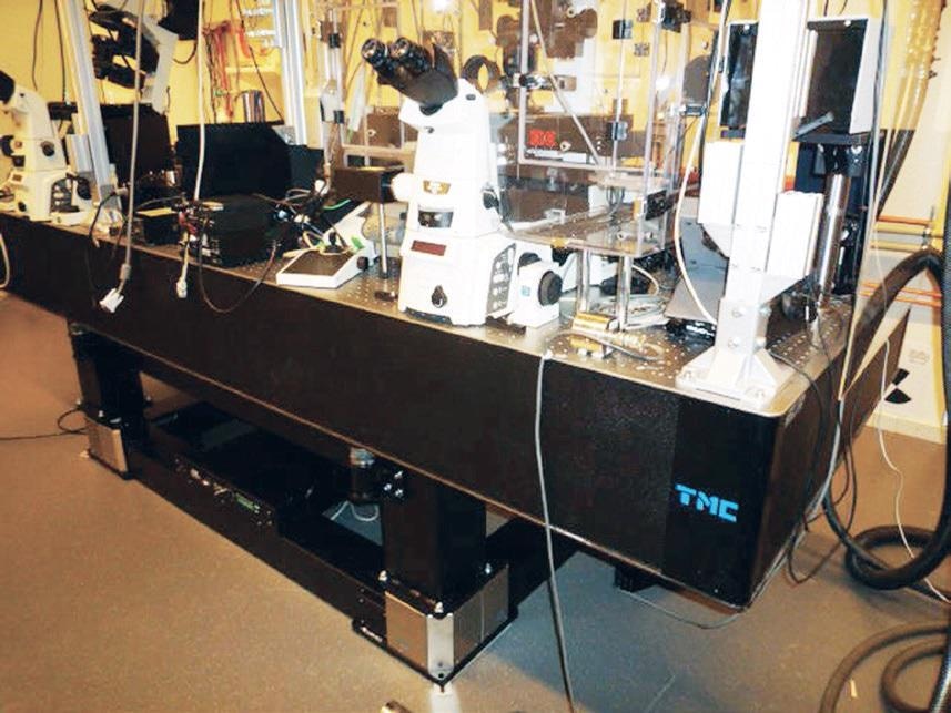
Photo courtesy of Uppsala University
References
[1] Jordan, S. and Anthony, P., Curr. Pharm. Biotechnology, 2009, 10, 515-521
[2] Yuan Shen et al., 2013, Advanced Materials Research, 706-708, 1423
[3] Abbondazieri et al, Nature, Nov. 24, 2005, 438(7067): 460–465.
[4] The authors thank Thomas Perkins for contributing this vivid before/after data.

This information has been sourced, reviewed and adapted from materials provided by TMC.
For more information on this source, please visit TMC.