SEM-EDS analysis, generally compared to automated mineralogical analysis, is considered the gold standard for quantifying textural properties and the amount of key ore minerals occurring in geological samples.

Image Credit: TESCAN USA Inc.
Representative samples of the ore are prepared, ground, and screened for basic screening. To do this, a cylindrical mount is constructed using precise size fractions implanted in an epoxy resin. After the resin has cured, the mounts are polished to attain a flat surface which is optimal for analysis using the electron microscope.
Using SEM, it is possible to perform a comprehensive analysis of the surface through a combination of various imaging and analysis techniques. The backscattered electron signal generates a high-resolution overview image of the sample. Using atomic number-based contrast, minerals comprised of heavier elements are displayed as brighter than those with lighter elements of lower atomic numbers.
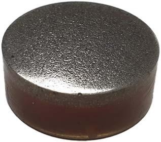
Figure 1. Polished resin block containing ore particles. Image Credit: TESCAN USA Inc.

Figure 2. Backscattered electron image of the grain mount surface. Brighter grains indicate a higher average atomic number. Image Credit: TESCAN USA Inc.
To determine which minerals are inside the sample, the distinctive X-Rays that the sample emits are analyzed using energy dispersive spectroscopy (EDS). This helps create detailed elemental maps of the sample using automated mineral analysis software, such as TESCAN TIMA software.
It is vital to gain a good understanding of the mineralogy of the geological deposit. SEM-EDS offers a relatively fast and simple way to evaluate the overall profitability of the ore deposit.
This information is indispensable to mineralogists as it offers a clear overview of the elements and minerals in the grain mount sample. A vast amount of similarly prepared samples can be analyzed using automated methods to deliver statistics of real value.
However, the images and mineral maps created using SEM analysis alone do not incorporate information relative to the 3D grain shape. Therefore, empirical models must be applied to evaluate the true grain size of the particles.
It is only possible to analyze one single cross-section of the sample at a time, which means that rare minerals appearing in extremely low occurrences may go undetected if they are not featured in a particular cross-section.
If mistakes were made during sample preparation, another potential issue arises: heavier grains may sink to the bottom if an epoxy-based grain mount is ill-prepared. This is due to the fact the bottom of the sample will be polished to become the sample surface. Therefore, during analysis, this density gradient can lead to the occurrence of denser phases such as native gold, galena, and other heavy minerals being grossly overestimated.
To ensure the acquisition of valuable 3D information, supplementary analytical techniques such as micro-computed tomography (micro-CT) can be used to carefully evaluate mineralogical samples. For example, a larger volume can be analyzed with micro-CT, meaning the entire grain mount or even unprepared rock core samples can be analyzed.
Based on the atomic number of the elements in the sample, microCT volumes have the tendency to show a 3D distribution of X-Ray attenuation akin to backscattered electron images. As a result, it is possible to generate results that show 3D shape, volume, and distribution with a grey-level-based segmentation of the minerals occurring in the sample.
In cases where the grey level contrast is sufficiently clear, micro-CT analysis can supply the required information for 3D mineralogical analysis of samples. However, when the atomic numbers of minerals are similar because they are comprised of elements close together in the periodic table, standard micro-CT cannot differentiate and generate meaningful data on the occurrence of these minerals.

Figure 3. 2D mineral maps produced with TESCAN TIMA. Left: all minerals. Right: Gangue phases are represented using grey while ore minerals are highlighted in blue. Image Credit: TESCAN USA Inc.
This article demonstrates how to use TESCAN Spectral CT to generate contrast for phases of similar density (overlapping gray level) and how spectral CT can be used to identify the presence of heavy elements in important ore minerals.
Materials and Methods
To demonstrate the versatility of this approach, two different samples were analyzed: 1) a grain mount sample with a diameter of 3 cm and 2) an unprocessed half-drill core with a 5 cm diameter. The grain mount sample was polished and analyzed using the TESCAN TIMA (Figure 3).
TIMA analysis was able to separate three primary ore materials apart from the silicate gangue: cassiterite (SnO2 ), a tin ore, scheelite (CaWO4 ), a tungsten ore, and tantalite ([Fe,Mn][Nb,Ta]2 O6 ), a tantalum ore.
Subsequently, using the TESCAN UniTOM XL SPECTRAL, standard and spectral CT scanning techniques were applied to the same section. TESCAN Spectral CT enables K-edge imaging for elements possessing a higher atomic number across the entire sample volume. The K-edge is denoted by an abrupt increase in X-Ray absorption, resulting from the binding energy of the most central electron shell.
This generates precise elemental information to complement the structural information acquired using standard micro-CT imaging. The full core sample is a 5 cm diameter, 20 cm height, gold-bearing sample. The distribution and volume of the gold particles inside are unknown, which makes these values of interest when conducting a non-destructive investigation.
This gold-bearing sample was scanned with the UniTOM XL SPECTRAL, using both standard CT and spectral CT.
Reconstruction of the standard CT scans was performed using Panthera™. For 3D visualization and analysis, both Panthera™ and ORS Dragonfly were used. The TESCAN PolyDET II detector was used to capture Spectral CT images which were analyzed using the TESCAN Spectral Suite™.
Results and Discussion
Grain Mount Sample
The standard CT scan of the grain mount sample was carried out with application of an accelerating voltage set to 160 kV in combination with 15 W power and a voxel size of 13 µm. The full volume of the grain mount can be analyzed with the resulting scan.
The key minerals (scheelite, tantalite and cassiterite) can be clearly identified and separated from the bulk silica minerals. The grey value allows for easy segmentation.
Consequently, it can be deduced that these minerals comprise 0.9 vol.% of all mineral grains across the sample. It is also possible to analyze the segmented grains to gain insight into the important parameters such as volume, sphericity, orientation, etc. The segmented heavy minerals are color-coded according to their size as displayed in Figure 4.

Figure 4. Left: volume render of the conventional CT scan of the grain mount. Right: dense particles color-coded to size. Image Credit: TESCAN USA Inc.
The resulting dataset also demonstrates how non-destructive 3D analysis can complement conventional 2D analysis methods. When inspecting a lateral view of the sample and assessing the distribution of dense grains in that direction using a maximum intensity projection, it becomes evident that there is an amelioration of dense particles toward the sample’s surface.
Only a small amount of very fine grains of the ore minerals are present in the bottom half of the sample which is mostly made up of silica gangue. This indicates that there is an overestimation in the electron microscopy data toward the three important minerals in the sample. This bias is a result of the gravitational settling of the heavy particles when the sample was being prepared.
As displayed in Figure 5, improper sample mounting leads to incorrect conclusions: where surface analysis indicated that over 12 percent of the mineral grains were thought to be cassiterite, scheelite, or tantalite, the 3D analysis of high grey value particles showed this volume fraction to be less than one percent.
Figure 5 reveals that the number of particles was overestimated and the miscalculations also relate to the particle size, as larger particles rapidly sink to the bottom of the epoxy during settling.

Figure 5. Maximum intensity projection in the lateral view of the sample, clearly showing an enriched layer of ore mineral grains at the sample’s surface, and a gradual to no occurrence of dense grains toward the bottom. Image Credit: TESCAN USA Inc.
It is crucial that these minerals are differentiated from one another for a proper and complete characterization of the ore. As shown in Figure 6, which displays a micro-CT slice through a few mineral grains, the tin ore can be clearly distinguished from the other two key minerals, as the average atomic number of cassiterite (40.1) is considerably lower than that of scheelite (51.8) and tantalite (51.9).
This captures an initial differentiation in the minerals of 30 vol.% of cassiterite and 70 vol.% of scheelite/tantalite. However, according to the attenuation of both scheelite and tantalite, it remains unknown how to identify which mineral the brightest grey values in the dataset relate to. Moreover, TIMA analysis revealed that several of the Ta and W ore grains are in the smallest grain fraction. This supports the claim that the partial volume effect makes grey value-based segmentation unreliable.
 .
.
Figure 6. Zoomed view shows a micro-CT slice of the grain mount at two locations. The majority of grains in these images correspond to the tin ore cassiterite. It is not possible to tell the mineral to which the two brighter grains belong. Image Credit: TESCAN USA Inc.
To correctly identify the mineral within this dataset, spectral CT was used to perform further analysis. Spectral CT imaging makes it possible to analyze the spectrum of both highlighted grains, as shown in Figure 6, to determine which is the predominant mineral at that location using K-edge imaging.
Since Ta and W are closely related elements on the periodic table, the absorption curves of Ta and W display k-edges at 67.4 keV and 69.3 keV, respectively.
The spectra of the bright minerals highlighted in Figure 6 are displayed in Figure 7. This reveals that one of the grains is scheelite as it contains W, which leads to the conclusion that the other grain is the Ta-containing tantalite.

Figure 7. Identification of the mineral grains from Figure 6 as W- or Ta-bearing mineral grains. Image Credit: TESCAN USA Inc.
Since spectral CT is a complete 3D method, the entire 3D spectral volume can be segmented for viewing. Resultingly, all scheelite and tantalite grains across the entire dataset are differentiated (Figure 8).
, tantalum ore (green) and tungsten ore (red).")
Figure 8. Segmentation of all grains in tin ore (yellow), tantalum ore (green) and tungsten ore (red). Image Credit: TESCAN USA Inc.
This approach enables the calculation of the volume fractions of every single one of the valuable minerals across the sample. By remove the effect of partial volume, the tin fraction can be adjusted to 83 vol.% of the dense fraction in contrast to 70 % with standard CT methods.
Tantalum (tantalite) appears in 13.9 vol.% of the dense fraction and 2.6 vol.% contains tungsten (scheelite). A review of the dense fraction, which makes up just 0.9 vol.% of all grains, shows that the sample comprises 0.75 vol.% cassiterite, 0.12 vol.% tantalite, and 0.02 vol.% scheelite.
Full Core Sample
The previous example demonstrates the benefit of 3D spectral CT on samples prepared routinely for electron microscopy; the method can also be applied to screen unprocessed samples.
In the following, the TESCAN UniTOM XL SPECTRAL was used to analyze a 5 cm diameter core sample – divided across its longest axis – to identify gold grains inside the sample. Sourced directly from a mine, the sample was sliced in half to reveal a flat surface for further analysis, such as X-Ray diffraction and micro-X-Ray fluorescence.
Initial tests showed that the sample contained sparse amounts of gold distributed in relatively small volume fractions of 100 µm and smaller. The sample was initially screened for 40 minutes at 30 µm voxel size (Figure 9) to see if a CT scan could show any dense particles that could potentially be gold.
As gold is the highest attenuating material inside the sample, in principle, the gold could be detected by segmenting the sample based on the dataset’s brightest grey values.
However, segmentation at this resolution is not advised due to the small dimensions of the gold grain because the partial volume has a direct impact on the grey value of potential gold particles. As a result of the partial volume effect, smaller gold grains seem to possess the same grey value as larger grains with lower attenuation coefficients, as displayed in Figure 9.

Figure 9. Volume render of the gold-containing rock core. Image Credit: TESCAN USA Inc.
By analyzing all potential gold particles with spectral CT, particles containing gold can be identified with absolute certainty. As Figure 9 shows, when analyzing the spectrum of the small particle, a clear absorption edge at 80.7 keV can be seen, signifying the presence of gold in that location. The larger particle lacked this absorption edge, which concludes that this particle was not a gold grain.
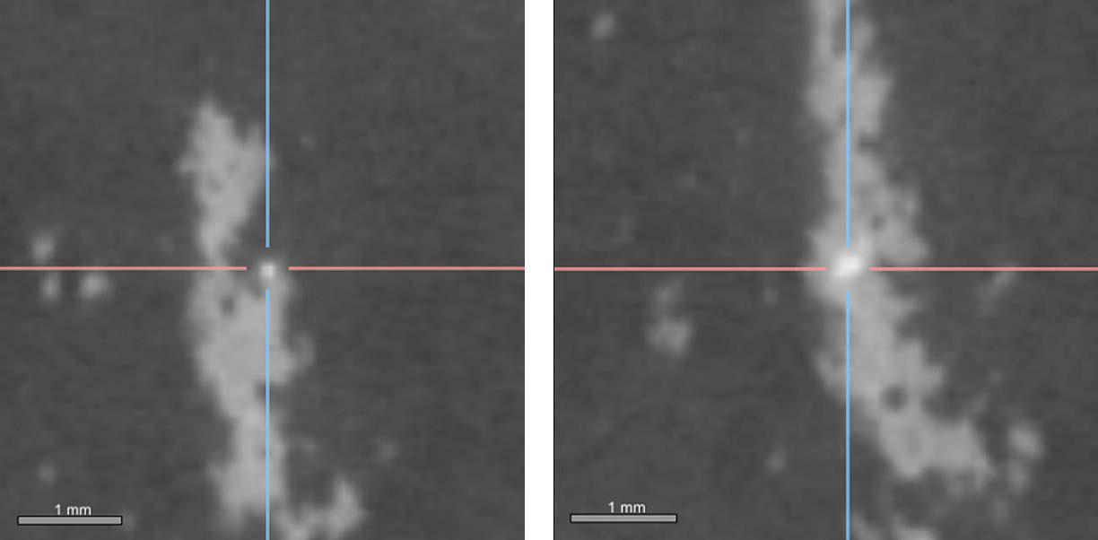
Figure 10. A small (80 μm size) potential gold grain (left) has the same grey value as a larger (300 μm size) grain that’s most likely not gold (right). Image Credit: TESCAN USA Inc.

Figure 11. Spectral analysis of targeted grains inside a large core indicates the presence of gold. Image Credit: TESCAN USA Inc.
Conclusions and Outlook
A powerful method for compositional analysis of geological specimens can be achieved through a combination of standard micro-CT and spectral CT. Spectral CT has the capacity to quantify the number of valuable ore minerals inside a sample without having to prepare the sample.
In addition, spectral CT supports conventional 2D analysis techniques, by generating valuable 3D information on grain shape, size and distribution. When the concentration of key minerals is extremely low, microCT has the capacity to rapidly scan large 3D volumes, making it a suitable sample screening method for these materials.
New advances in the field of spectral CT make micro-CT even more influential as a reliable analysis technique. This is due to the fact it is now possible to differentiate minerals that possess broadly similar X-Ray attenuation properties, making them easy to identify at any point inside a sample, both internally and externally.

This information has been sourced, reviewed and adapted from materials provided by TESCAN USA Inc.
For more information on this source, please visit TESCAN USA Inc.