Additive manufacturing (AM) is an advanced manufacturing technique with plenty of promise that requires the development of new methods for inspection and validation. The technique of dynamic micro-CT involves in situ collection of uninterrupted 3D data and high temporal resolution. It is considered the perfect method for assessing the complex and intricate geometries often found in AM parts.
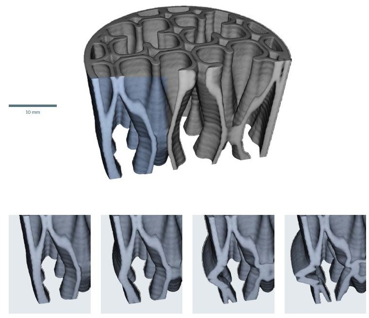
Image Credit: TESCAN USA Inc.
This article outlines the collection of uninterrupted 3D data on several 3D-printed plastic parts under a compressive load. Using the TESCAN UniTOM XL and dynamic CT for the data acquisition, it was possible to visualize the internal change occurring during the load testing with a high temporal resolution of 5.8 seconds/rotation.
Background
In recent years, the technical advantages of additive manufacturing have garnered considerable attention. AM techniques can produce complex and unique shapes not possible with conventional subtractive manufacturing and, in most cases, with greater efficiencies and reduced costs.
Even though there are many possibilities in this potential manufacturing paradigm shift, there are still many obstacles to ensuring that the quality of the final part meets its promise.
Besides the challenges faced throughout the production process regarding defects and dimensions, it is crucial to gain a better understanding of an AM part’s performance when in operation. This is particularly important when parts are subjected to specific external conditions such as heating or loading.
For parts or items with complex and hidden structures, conventional mechanical testing methods offer a general overview of the bulk mechanical properties, but how this impacts any individual features can only be evaluated by destructive methods at the end of the test. In this situation, it can only be inferred from the initial and final states of the part what happened during the test.
Dynamic Micro-CT and the Importance of Temporal Resolution
Micro-CT uses X-Rays to collect 3D data and is known for being extremely useful for non-destructive analysis. As the technique has advanced, it is now being used to acquire a greater understanding of what changes occur in 3D structures while undergoing mechanical testing.
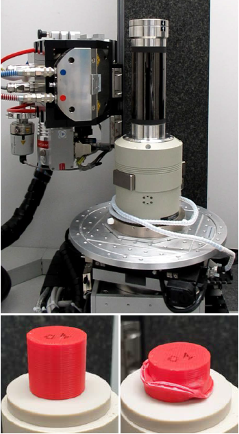
Figure 1. (top) Deben load cell installed in UniTOM XL; (bottom left) uncompressed sample; (bottom right) compressed sample. Image Credit: TESCAN USA Inc.
In situ micro-CT facilitates the three-dimensional study of processes inside a sample under various external conditions that are constantly changing, such as load or temperature. However, this technique has been mostly used in interrupted process applications, also known as time-lapse imaging.
To gain further insight, TESCAN uses the method of dynamic CT, which refers to the most state-of-the-art subset of time-resolved 3D X-Ray imaging. Dynamic CT leverages high temporal resolution, which involves continuous imaging of a sample as it is changing. There is also no interruption or pausing throughout the entire process.
Dynamic CT and in situ time-lapse methods can be differentiated in the same way a smooth video can be distinguished in comparison to a stop motion animation. The stop motion has key information missing between individual time points and the temporal resolution is not sufficient to properly capture every detail. On the other hand, the smooth video has adequate temporal resolution to fill in the gaps and tell a complete story.
Similarly, the benefits of dynamic CT when performing continuous acquisition on micro-CT rests is its capacity to perform uninterrupted, real in situ experiments. The high temporal resolution leveraged by dynamic CT enables the user to capture data throughout the entire process. This prevents any undesirable effects, such as relaxation, which may occur if a pause is required each time a tomogram is collected.
Materials and Methods
To demonstrate how valuable dynamic CT can be in additive manufacturing applications, a study of in situ 3D deformation of three plastic parts printed with different infill patterns was conducted. Each of the infill patterns evaluated make up the internal support structure of the sample, which goes unseen.
Using a TESCAN UniTOM XL micro-CT, 220 tomograms over 22 minutes were captured with a temporal resolution of 5.8 seconds per sample rotation and a voxel size of 59 µm. Each sample was continuously compressed throughout this process.
A Deben CT5000RT was leveraged as the load cell. During continuous rotation and data collection, a TESCAN in situ interface kit for “no-cable-wrap” operation was used. Images of the load cell and the initial and final states of one of the samples are displayed in Figure 1.
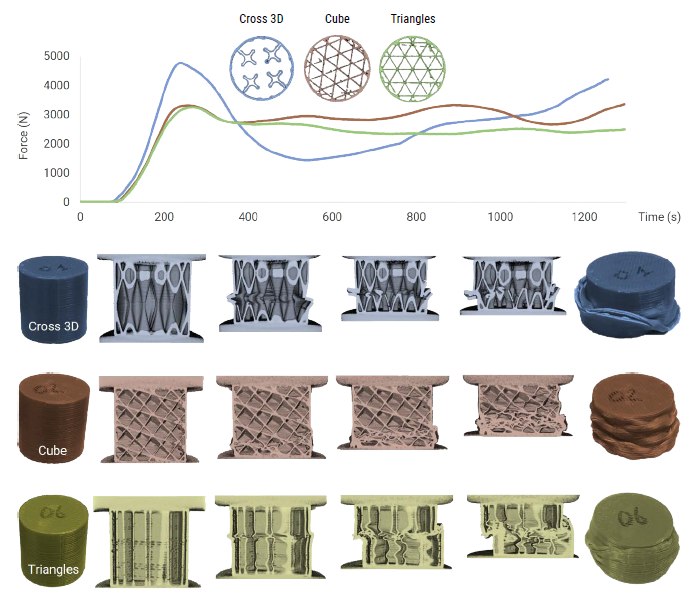
Figure 2. (top) load curve showing measured force over times; (bottom) example images of each sample at different times during the test. Image Credit: TESCAN USA Inc.
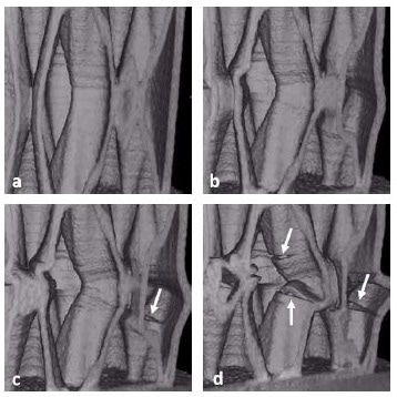
Figure 3. Detail of layer separation on the Cross 3D sample at different time points during compression. a) 3.5 minutes b) 5.8 minutes c) 6.5 minutes d) 8.3 minutes. Image Credit: TESCAN USA Inc.
Infill patterns are required for supporting the layer integrity of each part, but the patterns also influence the performance of 3D-printed parts. There is not a ‘one size fits all’ infill pattern for all applications.
The final shape and application of the part guides the decision of what pattern to use. Furthermore, the printing technique, time, and cost also play a major role in this process. For this study, three commonly used infill patterns were chosen: Cross 3D, Cube, and Triangle.
Results and Discussion
The load curve vs. time for the three different infill patterns – Cross 3D, Cube, and Triangle – are displayed in Figure 2, along with representative 3D renders and virtual slices for each sample at different time markers. There are several immediate insights that can be taken from both the load curve and the images.
From the load curves, the similarity in behavior seems consistent across each pattern, but the Cross 3D pattern seems to initially carry a larger load before showing a sudden decline compared to the other two samples, before it recovers again.
The 3D visualization reveals an initial collapse in a single layer as unrestrained compression occurs in that layer until it collapses onto the next layer. Observing the final state, it is clear that most of the deformation took place in a small region, with the largest amount of deformation occurring in the outer walls.
Conversely, the overall geometry integrity of the cubic sample seems to be intact, with some localized buckling occurring throughout. Initially, a failure in a single layer can be seen toward the bottom, but a closer inspection of the progression reveals multiple layers collapsing throughout the height of the sample.
Notably, the triangle infill shows completely different results, with a clear shear occurring where the sample “slides” along a favored direction. Alongside the 3D observations of the entire sample, the visualization enables the user to focus on specific points of the sample during certain time frames and observe any localized changes.
For example, a closer look at some of the changes in the Cross 3D sample, as displayed in Figure 3, reveals clear separation between individual layers as the load increases. Here, progression of failure is observed over ~5 minutes where defects are plain to see. These specific failures suggest a lack of fusion between certain layers which signals a remodeling of the initial build parameters.
Finally, with samples like these, a multi-scale approach, which enables a better understanding of the microstructure in specific locations, can be taken, for instance, where higher spatial resolution scans are conducted before and after the mechanical test. This can be seen when evaluating the triangle-infilled sample. Prior to compression, a higher spatial resolution volume of interest scan (VOIS) was performed at 8.5 µm voxel based on information acquired from an initial lower resolution scan.
Within the Panthera™ visualization package, the lower resolution scan displayed anomalies on the surface of one of the struts. Through an intuitive workflow, this region was chosen for a semi-automated higher resolution scan. The multi-scale approach is displayed in Figure 4.
With the higher resolution results, it is possible to see individual build layers more clearly, which show indications of an abnormality in the build pattern which creates voids. These voids could be points of initial failure, potentially being the cause of the shearing behavior observed in the dynamic CT results.
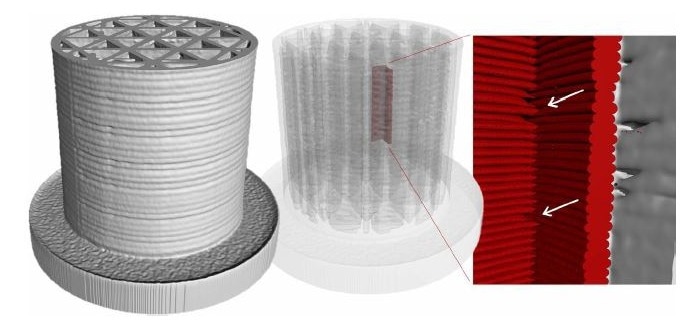
Figure 4. (left) overview scan of the full sample; (center) overlay of VOIS (red) showing location within the full sample; (right) and detail of print defects (voxel size of 8.5 μm). Image Credit: TESCAN USA Inc.
Summary
As additive manufacturing progresses, with complex and intricate geometries becoming commonplace, having the right tools to gain further insight and understanding as to how these parts perform under different conditions is crucial.
With dynamic CT, which is available across the entire line of TESCAN micro-CT solutions, it is possible to acquire continuous and uninterrupted 3D data during these processes. As discussed in this article, the TESCAN UniTOM XL, in combination with dynamic CT, facilitated a study of the changes internal and concealed structures of 3D printed parts experiences when subjected to compression loading.
This illustrates the value of dynamic CT as a means to better understand what internal and unseen changes contribute to the overall performance of a 3D-printed part as it undergoes mechanical loading.

This information has been sourced, reviewed and adapted from materials provided by TESCAN USA Inc.
For more information on this source, please visit TESCAN USA Inc.