A paper recently published in the journal Energies reviewed the use of grid-forming (GFM) converters to realize grid stability in power systems.

Study: Grid-Forming Converters for Stability Issues in Future Power Grids. Image Credit: Brian Guest/Shutterstock.com
Background
The power system has traditionally depended on synchronous generators (SGs) to maintain grid stability and provide inertia. However, maintaining grid stability has become challenging in the past decade due to a lack of inertia with the rising integration of power-electronics-interfaced renewable energy sources (RES) within power systems.
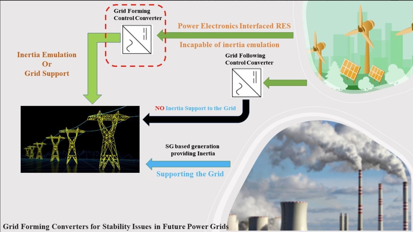
Currently, grid-following (GFL) converters are primarily used in the power system to maintain grid stability due to the assumption that the system stability is regulated by inertial sources. However, such an assumption is ineffective for the low-inertia grids in the future.
GFM converters are considered a potential solution to support the low-inertia grids as they can mimic the functionalities of synchronous machinery. Different configurations and topologies of GFM converters were already proposed to address the major grid stability-related issues in low-inertia grids.
Several studies were performed to analyze the performance of GFM converters for small signal stability. However, the performance of GFM converters for large-signal stability has not been studied extensively. Moreover, no comparative studies were performed combining all GFM configurations to mitigate large-signal stability issues.
In this study, researchers combined and compared all existing GFM control schemes in the context of large-signal stability issues to facilitate further research and development of GFM converters for the stabilization of the low-inertia grids.
GFM Converters and the Stability of Power System
Large-signal Stability Issues
The GFM converter experiences overcurrent problems during a large-signal disturbance such as a 3-phase alternating current (AC) fault, which necessitates the adoption of current limiting strategies to ensure safe operation. The latched limiter and the instantaneous saturation limiter are the major strategies that can be used to limit the current.
The operation mode of the GFM converter switches from voltage source mode to current source mode owing to the large-signal disturbance. To stay in the voltage source mode, the converter current must remain within the limits of the converter. Additionally, the inertia-providing GFM converter power system is a second-order system that can produce power oscillations in absence of sufficient damping, which affects the stability performance of the converters.
Different methods, such as the shifting control method in which the GFM converter switched to GFL control mode during the large-signal disturbance, were proposed to address these stability issues.

Image Credit: Su, W et al., Energies
A virtual impedance-based voltage-limiting method was implemented in a study in which an output impedance was added to reduce the reference voltage when the current crossed the acceptable limits.
This method decreased the reference current and prevented saturation. However, specific stabilities, such as voltage and frequency stability, must be understood to thoroughly comprehend the stability dynamics.
Frequency Stability
The objective of frequency control or stability is to maintain the frequency at the set or nominal value. Frequency nadir and the rate of change of frequency (RoCoF) are the major frequency control and monitoring indicators. A higher RoCoF and frequency nadir outside the allowable limits are often observed in low-inertia grids.
The risk of high-frequency swings for converter-based generation of renewable energy can be addressed using GFM converter controls. These GFM controls provide the primary frequency control and inertial response by identifying the frequency swing and regulating the power injection to maintain the set/nominal frequency value.
A reserve capacity must be maintained to mitigate the load and generation imbalance to attain a faster frequency control after a large-scale disturbance. In the inverter-interfaced sources, the reserve capacity can be maintained by operating the inverter below the rated value or through inverter-interfaced batteries.
The lack of proven and matured grid forming solutions is restricting the implementation of hierarchical control strategies in bulk grids and inverter-interfaced microgrids. Thus, more research is required to realize the GFM converters in low-inertia grids at the bulk level.
Voltage Stability
Voltage stability is maintained by keeping the voltage of the power system within the allowable range. Existing GFL converters experience dynamic voltage stability issues in low-inertia grids due to the reduction in the voltage when the power order increased at the point of common coupling (PCC).
The GFL control of the system relies on the grid for frequency and voltage regulation. Thus, GFM converters are considered the only suitable and potential option that can provide voltage and frequency services. The voltage control or regulation in GFM converters involves decreasing or increasing the reactive and real power.
GFM converters often provide voltage control through reactive power owing to its enhanced sensitivity/reactive power voltage. Thus, these converters can provide voltage support even in weak inertial grids. Voltage stability is also important in developing direct current (DC) grids and microgrids. In microgrids, virtual impedances were added to decrease the parameter sensitivity to achieve voltage control.
However, GFM-based approaches cannot be applied to mitigate the voltage stability issues in the future microgrids and bulk grids as such grids will be distributed geographically and the fault current of GFM converters is low. Thus, new approaches with specific stability criteria must be developed for future systems.
GFM Converter Topologies
GFM converters are characterized depending on the controller structure. These converters possess distinct properties, such as independent frequency and voltage control, low output impedance, and black start capability, that make them suitable for grid strengthening, providing inertia, and inverter-based grids.
Synchronverter
Synchronverter/ virtual synchronous machine (VSM) virtually operates on the principle of synchronous machine. The VSM is composed of power and control blocks. The power block comprises the converter and its interconnection with the grid, while the control block performs the generation, regulation, and calculation of pulse width modulation (PWM) pulses for the converter gate driver.
All SG parameters are modeled in a synchronverter. Thus, all existing and matured control strategies designed for SG can also be applied to a synchronverter. A synchronverter can be operated in the GFL or GFM mode as it does not follow a current or voltage reference.
Matching Control
Matching control topology regulates the DC link and uses a DC link in place of an SG model to drive the harmonic frequency oscillator. A controller based on the embedded internal oscillator model drives the inverter modulation and the DC link voltage is used to monitor the power balance.
Active power tracking is achieved by regulating the DC, which leads to voltage control and oscillator frequency. Matching control only uses DC-side measurements that eliminate processing delays. The duality of the machine’s angular velocity and the converter DC voltage is also referred to as matching control.
Virtual Oscillator Control (VOC)
VOC is based on the non-linear oscillator dynamics emulation in the inverter control. VOC is similar to matching control, except for the use of time-domain signals for the regulation of voltage in place of phasors. The PWM signals for the GFM converter are generated using the terminal voltage of the oscillator. VOC possesses all droop control features and provides a superior load-sharing capability and voltage regulation.
Dispatchable Virtual Oscillator (dVOC)
dVOC enables users to establish power setpoints for the inverter. However, dVOC functions in the VOC mode if the set points are absent.
Direct Voltage (V-f) Control
V-f control is the best option for passive grid applications, such as islanded grids, as the output frequency and voltage remain under closed-loop control. However, this GFM technique has limitations when implemented in active grids as it lacks power-sharing ability. V-f control consists of dual- and single-loop control modes.
In the single-loop control mode, the frequency and voltage reference values generate the converter output voltage, while in the dual-loop control mode, the output voltage relies on the cascaded loops of voltage and current, which provide the current-limiting ability of the dual-loop control mode. The single-loop mode can be applied for the regulation of AC voltage in GFM applications and is advantageous when implemented in master-slave topology.
To summarize, this review provided a roadmap for further research on the feasibility of using GFM converters to overcome stability challenges, specifically large-signal stability, in future/modern RES-dominated low-inertia grids.
Reference
Su, W., Liu, G., Chaturvedi, S. et al. Grid-Forming Converters for Stability Issues in Future Power Grids. Energies 2022. https://www.mdpi.com/1996-1073/15/14/4937
Disclaimer: The views expressed here are those of the author expressed in their private capacity and do not necessarily represent the views of AZoM.com Limited T/A AZoNetwork the owner and operator of this website. This disclaimer forms part of the Terms and conditions of use of this website.